System 2, Area 3, Areas 1 & 2 – Cloud Electronics DCM1 User Manual
Page 12: Area 4
DCM1 & DCM1e Installation and User Guide v1.0
12
System 2
AREA 3
POWER
AMPLIFIERS
OTHER
AREAS
CD
JUKEBOX
OFF-AIR
RECEIVER
MP3 PLAYER
DOCK
MUSIC
SERVER
CDR-1
CDR-1
CDR-1
INPUT 1
INPUT 6
INPUT 4
INPUT 8
INPUT 2
INPUT 7
INPUT 3
INPUT 5
CDPM/PM
MIC 1
MIC 4
MIC 2
MIC 3
PAGING MIC
PAGING ACCESS
CDR-1
PORTS
1
2
3
4
ZONE 5
ZONE 3
ZONE 2
ZONE 6
ZONE 8
ZONE 4
ZONE 7
ZONE 1
AREAS 1 & 2
ME-1
ME-1
PARTITION
AREA 4
CDR-1
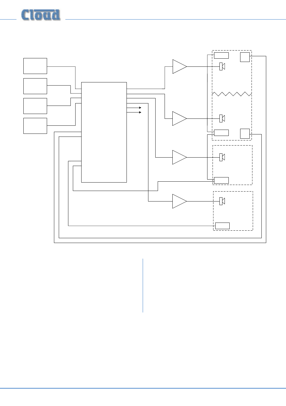
This shows a more complex system, which illustrates some additional DCM1 installation possibilities. Points to note:
•
The large area has two CDR-1 remote controls in the
same zone; typically, these might be adjacent to doors at
opposite ends of the room.
•
Two of the areas are separated by a folding partition
which may be removed to create one large space. By
assigning these two zones to a Group within the DCM1,
the two zones can be treated as one for audio purposes
when the partition is removed and return to two
separate zones when it is reinstated.
•
Each half of the partitioned area also has an ME-1 mic
input module. Because these have been wired back to
the DCM1 independently, each can be made available
to their respective room halves as and when required.
Alternatively, it may be that they are only required
when the partition is folded back; in this case they are
activated for the Group instead.