Description of front panel – Cloud Electronics DCM1 User Manual
Page 14
DCM1 & DCM1e Installation and User Guide V1.0
14
Section 2: Installation
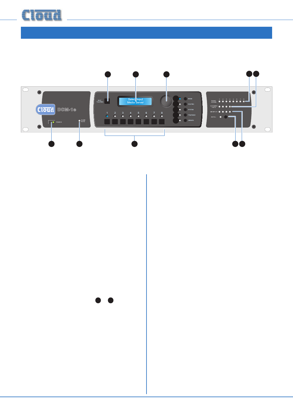
Description of front panel
1
15
5
14 13
12 11
2
4
3
10
9
8
7
6
1.
POWER button: applies DC power to the DCM1
(note external PSU).
2.
LCD display: 2 x 16-character backlit blue LCD display
used in all control and menu functions.
3.
Rotary control: for adjusting unit parameters via the
display. The control also has a “press” action, which is
required for some front panel operations.
4.
Next Function button: used to scroll through the
various functions of each menu.
5.
Numeric buttons 1 - 8: the operation of these buttons
varies with the selected menu function. In many of them
they represent Zones 1 to 8, each button selecting a
zone that the menu function will apply to. In others, they
may represent Inputs 1 to 8, for example. Each button
has an associated blue LED to indicate the current status
of that zone or input for the function.
The menu system is divided into five groups, each of which is
selected by one of the menu buttons
6
to
10
. An associated
blue LED indicates selection.
6. MUSIC: gives access to per-zone source selection,
level control, EQ, maximum and minimum levels, and
input gain per-input.
7. ROUTING: Allows per-zone mic enabling and input
masking, plus other installation-specific functions.
8. SYSTEM: system menu includes enabling of
CDR-1 installer mode per-zone, mono/stereo
selection for Zones 1 & 2, RS-232 port set-up, zone
and input naming, security key set-up, etc.
9. PRIORITIES: allows assignment of priority inputs
(including paging inputs) and adjustment of the
DCM1’s operation when priorities are active.
10. GROUPS: the Group menu allows assignment of
Zones to Groups, and defined Groups to be enabled.
11. Paging Access: eight LEDs (one per zone) which
illuminate when a zone is selected for paging from an
external paging microphone.
12. Extension Ports: four LEDs corresponding to the
Extension Ports of Line Inputs 1 to 4. These LEDs
illuminate when a LE-1 or BE-1 remote input module
is connected, and the input to which it is connected is
enabled for the currently selected zone.
13. Mic Inputs: four LEDs corresponding to Mic Inputs
1 to 4. These LEDs illuminate when an ME-1 remote
input module is connected, and the input to which it is
connected is enabled for the currently selected zone.
14. Install button: activates Installer Mode. Allows access to
the menu functions which are intended to be unavailable
to the user. A key needs to be entered on the numeric
buttons for Installer Mode to be active.
15. Music Mute LED: illuminates when an external Mute is
applied at the Music Mute connector (normally linked to
Fire Alarm or other emergency system).