Cdr-1 remote control plates, Dcm1 & dcm1e installation and user guide 19, Network diagram 1 – Cloud Electronics DCM1 User Manual
Page 19: Network diagram 2
DCM1 & DCM1e Installation and User Guide
19
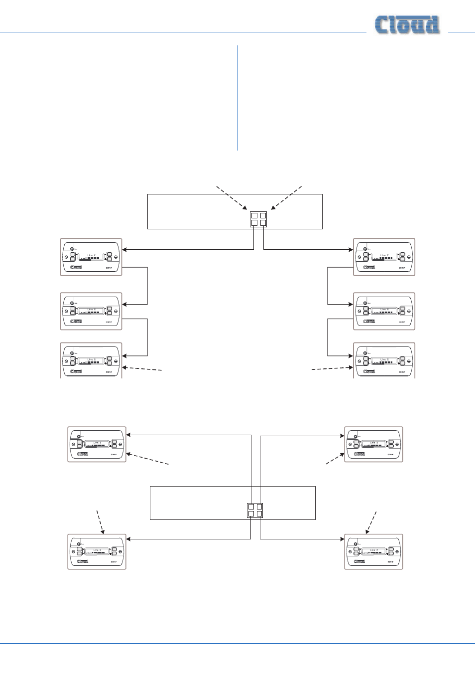
CDR-1 Remote Control Plates
Multiple CDR-1 or CDR-1F remote control plates may be
connected to the DCM1 either by wiring them directly and
individually, or by “daisy-chaining” them together. In most
installations, a combination of these methods is likely to
be the most convenient solution from the point of view of
practical cabling. The diagrams below illustrate the types of
wiring schemes that may be employed; almost any variation
on these is permissible.
CDR-1 PORTS
PORT
A
PORT
A
PORT
B
PORT
B
Termination ON
All other terminations are OFF
Port A termination ON
Termination ON
Port B termination ON
DCM1
IN
IN
IN
OUT
OUT
IN
IN
IN
OUT
OUT
Network Diagram 1
CDR-1 PORTS
PORT
A
PORT
A
PORT
B
PORT
B
Termination ON
All other terminations are OFF
Termination ON
Termination ON
Termination ON
DCM1
IN
IN
IN
IN
Network Diagram 2