Third-party paging systems, Ext psu – Cloud Electronics DCM1 User Manual
Page 25
DCM1 & DCM1e Installation and User Guide v1.0
25
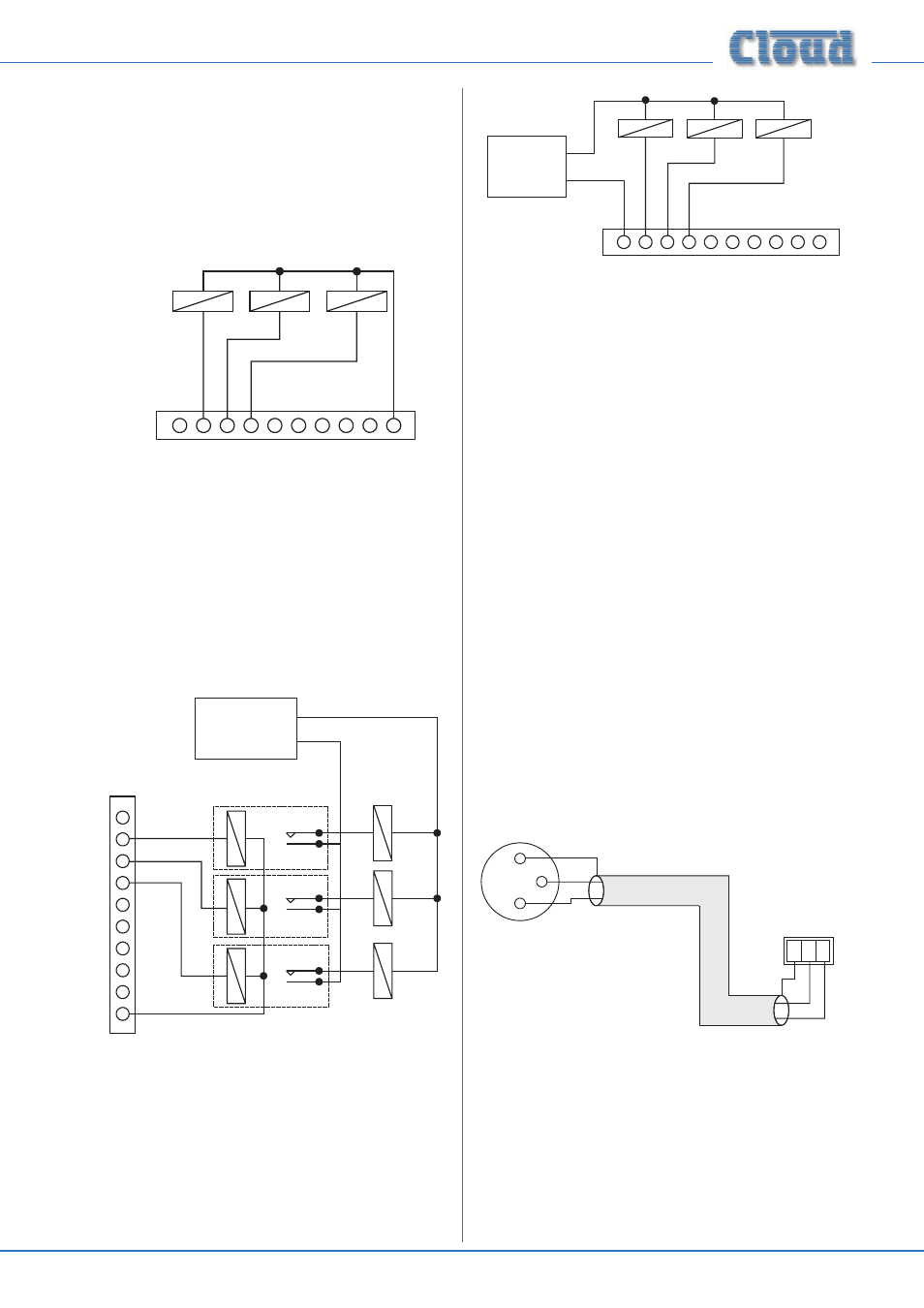
For many systems, the DCM1’s internal PSU will provide
sufficient current to activate an external relay in each zone.
Relays used in this way should have a coil voltage of 12 V DC
and draw less than 60 mA. The “Zone active” pins (2 - 9)
should be wired to one side of the level restoration relay
coils in the relevant zones. The other side of the relays should
be commoned together and connected to the +12 V pin (10).
The diagram below illustrates this.
PAGING ACCESS CONNECTOR
+12v
1
0v
8
6
5
4
3
2
7
External relays
(3 shown)
+
+
+
-
-
-
If the level restoration relay coils draw more than 60 mA per
zone, additional intermediate relays and an external PSU must
be installed. The basic wiring scheme shown above is used,
but now the “External relays” will be the intermediate relays
instead of the restoration relays themselves. The restoration
relays are then wired via the intermediate relays’ contacts to
the external PSU, providing full electrical isolation between
the DCM1 and the external level restoration system. This is
shown in diagram a) below:
Intermediate relays
(3 shown)
EXT
PSU
+
-
PAGING ACCESS CONNECTOR
+12v
1
0v
8
6
5
4
3
2
7
++
+
-
-
-
+
-
+
-
+
-
Restoration
relays
An external PSU should also be used in systems using relays
with a coil voltage higher than 12 V. The “Zone active” pins
are rated up to 24 V, so relays of up to 24 V may be switched
directly as long as the current drawn remains below 60 mA. If
either the maximum current rating of 60 mA or the maximum
voltage rating of 24 V is exceeded, intermediate relays must be
installed as shown in diagram b).
PAGING ACCESS CONNECTOR
+12v
1
0v
8
6
5
4
3
2
7
External
relays
(3 shown)
EXT
PSU
+
-
+
+
+
-
-
-
With all wiring schemes, attention must be paid to relay
polarity when wiring such a system, as the external relays will
almost certainly have a diode in parallel with the relay coil to
limit voltage spikes when the relay releases. Ensure that the
positive (+ve, or red) terminal of the relay coil is commoned to
the +12 V pin (pin 10) of the
PAGING ACCESS connector,
or the positive terminal of an external PSU. The negative (-ve,
or black) terminal of the relay coil should always be wired to
the “Zone active” pin (2 - 9).
See page 69 for details of the DCM1’s PSU capabilities.
Third-party paging systems
The DCM1 may be integrated with any paging system which
is able to provide a microphone feed and zone selection by
contact closure.
Paging microphone input
A 3-pin screw terminal connector provides an electronically-
balanced input for an external paging microphone. This should
be connected to the external microphone using good quality
low-noise microphone cable, using the wiring shown below:
1
2
3
1 2 3
+
-
+
-
SC
N
pin 1 ground
pin 2 hot
pin 3 cold
Balanced mic:
pin 1 ground
pin 2 cold
pin 3 hot
DCM1 Paging
Microphone input:
12 V phantom power is available at the input for microphones
requiring it (e.g., electret mics). Phantom power is enabled by
the internal jumper J24. The default setting for this jumper
is with phantom power OFF; move the jumper to the other
position to set phantom power ON. See page 65 for details
of jumper locations.
Level Restoration relay wiring: a) using intermediate relays
for isolation
Level Restoration relay wiring: b) using external PSU for
relays with a higher coil voltage than 12 v.