Pcb jumper locations and settings – Cloud Electronics DCM1 User Manual
Page 65
DCM1 & DCM1e Installation and User Guide V1.0
65
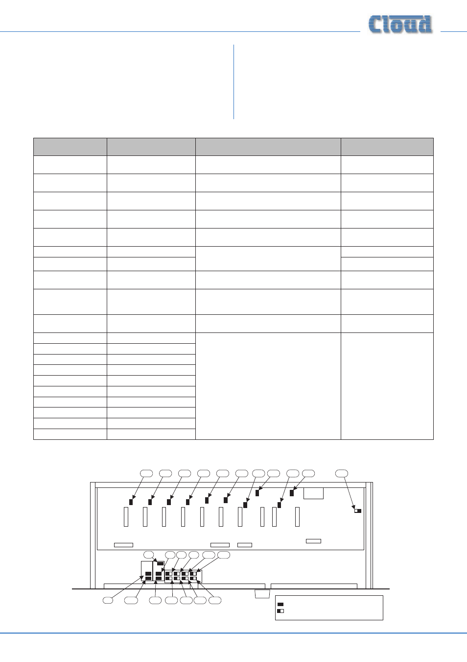
PCB jumper locations and settings.
The DCM1 has various internal jumpers, the setting of which
may require alteration during installation. The table below
lists each jumper and its purpose, together with the factory
default setting.
The diagram below the table shows the locations of the internal
jumpers (not to scale). In the case of the jumpers having two
possible positions, the black square in the symbol indicates
the default setting. If any jumpers need to be changed, undo
the eight screws securing the top cover of the DCM1, and
remove it. Use a pair of snipe-nosed pliers to gently remove
the jumpers, and to reposition them if necessary. Refix the
top cover using the original screws.
JUMPER
NAME
PURPOSE
DEFAULT
J2
PM/CDPM bus termination
ABSENT = PM/CDPM termination OFF
PRESENT = PM/CDPM termination ON
Present
J6
CDR-1 Port A bus termination
ABSENT = CDR-1 Port A termination OFF
PRESENT = CDR-1 Port A termination ON
Present
J7
CDPM ground link
ABSENT = PM/CDPM signal ground “lifted”
PRESENT = PM/CDPM signal ground connected
Present
J8
Reset Installer PIN
Reinstates original factory key for enabling Installer
Mode. Replace after use.
Off
J9
Force Factory Defaults
Reinstates original factory settings except Input/
Zone/Group names. Replace after use.
Off
J10
Bootloader baud rate: select 1
Changes baud rate for firmware updates. See table
page 70.
Off
J11
Bootloader baud rate: select 2
Off
J13
CDR-1 Port B bus termination
OFF = CDR-1 Port B termination OFF
ON = CDR-1 Port B termination ON
Present
J14
PM/CDPM power link
OFF = PM/CDPM power off
ON = DC power for PM/CDPM is available at
CDPM/PM IN connector.
Present
J24
Paging mic phantom power
OFF: paging mic phantom power OFF
ON: paging mic phantom power ON
Off
J25
EQ Module: Zone 1 R
Must be present if no EQ module is fitted
Present
J26
EQ Module: Zone 2 R
J27
EQ Module: Zone 3
J28
EQ Module: Zone 5
J29
EQ Module: Zone 6
J30
EQ Module: Zone 7
J31
EQ Module: Zone 4
J32
EQ Module: Zone 8
J33
EQ Module: Zone 1 L
J34
EQ Module: Zone 2 L
NOTE: J15, J16, J17 and J18 are reserved.
J2
J6
J13
J7
J14
J8
J9
J10
J11
J15
J16
J17
J18
J32
J27
J28
J30
J31
J29
J26
J34
J33
J25
J24
(UPPER PCB)
(LOWER PCB)
KEY:
Jumper with two possible positions; black
square indicates factory default setting.
Jumper with one position (i.e., present or not)