User mode, Installer mode, Navigating the menu system – Cloud Electronics DCM1 User Manual
Page 27: The menu structure is divided into five submenus, Music, Routing, System, Priorities
DCM1 & DCM1e Installation and User Guide V1.0
27
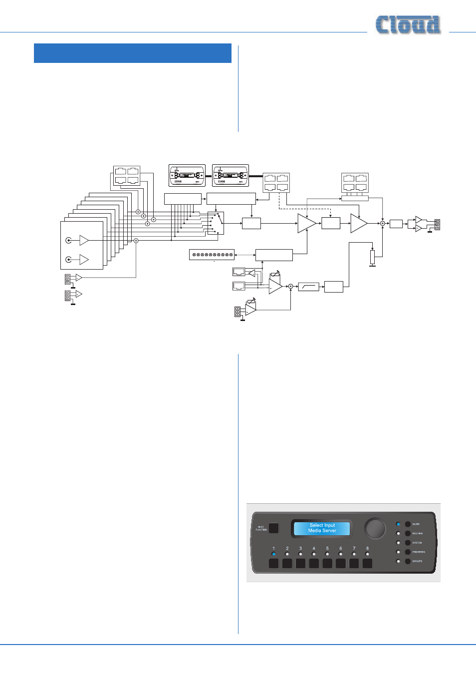
Section 3: Configuration
The DCM1 can be configured in a variety of ways to suit all
installed situations. Most configuration functions are accessed
through the menu system.
For convenience, the DCM1’s basic block diagram is repeated
here:
SPE
ZONES 1 AND 2 ARE STEREO
ZONES 3...8 ARE MONO
+
MIC PRIORITY
MICROPHONE INPUTS
EQ
VCA
ATTENUATOR
LINE 8
LINE 7
LINE 6
LINE 5
LINE 4
LINE 3
L
R
LINE 2
LINE 1
EXTENSION PORTS
1
2
3
+
+
LINE 8
BALANCED
R
L
LINE 1
LINE 2
LINE 3
LINE 4
MIC 1
MIC 2
MIC 3
MIC 4
GAIN
SOURCE SELECT LOGIC
CDR-1 PORTS
EQ CONTROL BY CDR-1 IS ONLY
AVAILABLE IN ENGINEER MODE
LINE PRIORITY
LOGIC
GAIN IS APPLIED
ACCORDING TO
SOURCE SELECTED
+
+
EQ
PAGING ACCESS
LOGIC
PAGING
MICROPHONE
INPUT
CDPM IN
CDPM THRU
+
PAGING ACCESS
Z2
Z1
Z3 Z4 Z5 Z6 Z7 Z8 0V
+12V
PORT
A
PORT
A
PORT
B
PORT
B
ONLY RIGHT STEREO SIGNAL
SHOWN FOR CLARITY.
ZONES 3...8. SIGNALS ARE SUMMED
TO MONO BEFORE SOURCE SELECT.
1
2
3
1
2
3
1
2
3
The menu system has two modes: User Mode and Installer
Mode.
User Mode:
User Mode is the default menu system mode which is available
at all times. It provides the user with the system control
functions needed on an everyday basis: music source selection
and level control for each zone, and group activation.
Installer Mode:
Access to Installer Mode is key-protected. The user should
ensure that only authorised staff who have been trained in the
DCM1’s configuration functions know the key. Installer Mode
allows adjustment of zone EQ, maximum and minimum levels,
microphone assignments, paging and priority parameters,
group membership and all other system setup parameters.
Installer Mode is selected by pressing the
INSTALL button,
and entering the key code via the numeric buttons below
the display in response to the prompt Enter Key. The
key is always a 4-digit number; only digits 1 to 8 are allowed.
The factory default key can be found in the Appendix; users
are strongly urged to change the key as soon as the system is
commissioned. A time-out applies to Installer Mode; if no keys
are pressed within 45 seconds, Installer Mode will cancel and
the unit returns to User Mode.
Navigating the menu system
The menu structure is divided into five submenus:
•
Music
•
Routing
•
System
•
Priorities
•
Groups
Each submenu is entered by pressing its dedicated button;
selection is confirmed by its adjacent LED.
The Routing, System and Priorities submenus are only
available in Installer Mode, as are most of the functions in the
Music and Groups submenus.
Navigation within all the submenus is performed with the
NEXT FUNCTION button, the rotary control and the
eight numeric buttons. In general,
NEXT FUNCTION
button steps through the selected submenu one function at a