Cdr-1 series remote control plates, Paging mic eq, Zone paging levels – Cloud Electronics DCM1 User Manual
Page 47: Setting up levels for best performance, Display contrast adjustment, User operation
DCM1 & DCM1e Installation and User Guide v1.0
47
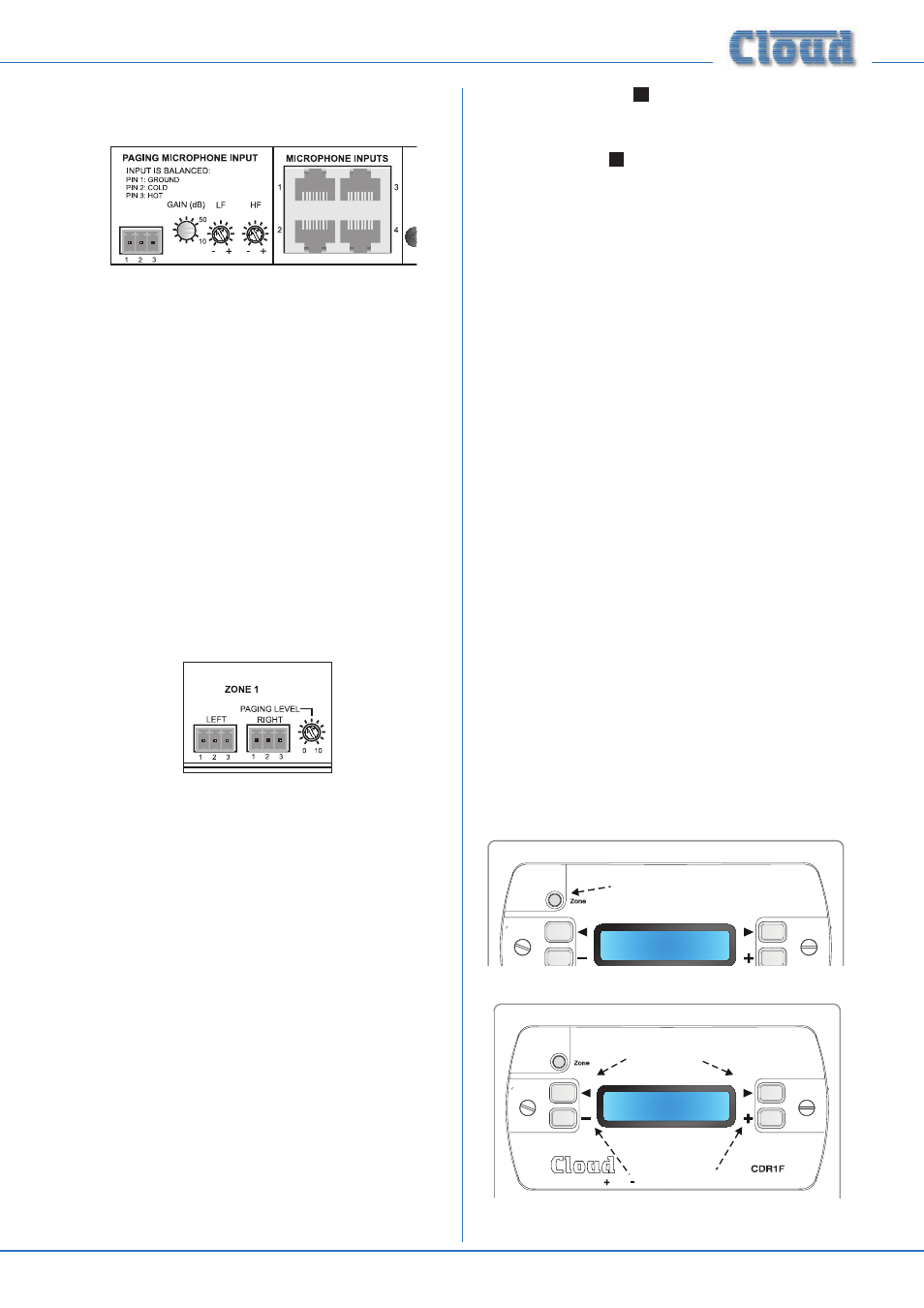
Paging mic EQ
HF and LF EQ controls for paging mics are provided. These
may be adjusted to reduce any extraneous noise in the vicinity
of the paging mic, or to compensate for any undesirable
colouration of the mic itself. The controls are adjacent to
the (third-party) Paging Mic Input, but they affect both
microphones connected to the Paging Mic Input and mic
signals from a PM Series paging mic (or CDPM) connected to
the
CDPM/PM ports.
The HF control provides up to 10 dB cut or boost above
5 kHz, and the LF control 10 dB cut or boost below 100 Hz.
Again, these controls should be adjusted using a test message,
ideally to the zone where the DCM1 is installed so that the
effect of the adjustment can be heard by the person making it.
As the controls affect both the CDPM/PM ports and third-
party paging mic inputs, a degree of compromise may be
necessary if a system requires both inputs to be used.
Zone Paging Levels
Each zone output connector has an adjacent preset control
which sets the volume for paging in that Zone. The
PAGING
LEVEL adjustment for a Zone is completely independent of
the music level adjustment for that Zone, the latter being set
by the user.
Setting up levels for best performance
To optimise signal levels through the DCM1 and obtain
the best signal-to-noise performance, we recommend the
following procedure is followed for adjusting music and paging
levels. (Numbers in squares refer to the rear panel diagram
on page 15.)
1. Choose a suitable music source, and set the Input Gain
of its input to 0 dB, via the Music menu in Installer mode.
2. Route this music source to a convenient Zone, and adjust
the Level in this Zone to 0 dB (i.e., maximum), again via
the Music Menu.
3. Adjust the gain of the power amplifiers feeding the
loudspeakers in that Zone so that the sound level in the
Zone is as loud as is likely to be required.
4. While making a paging call, adjust the rear panel Zone
Paging Level control
10
to achieve a sensible level in the
Zone. The message should be clear and undistorted.
5. If necessary, adjust the
PAGING MICROPHONE
GAIN control
6
as well. If at all possible, the test
message should be made by the person who will normally
use the microphone, as some people speak much louder
than others.
6. Repeat Steps 2 to 5 for the other Zones.
7. Repeat Step 1 for the other music sources.
Display Contrast adjustment
The display should be easily readable in most normal situations.
If it is necessary to alter the display contrast to improve
readability under extreme ambient lighting conditions, remove
the top cover (8 screws) and locate the trimpot at the left-
hand end of the PCB mounted directly behind the front panel.
This can be adjusted as required. Replace the cover using the
same screws.
CDR-1 Series Remote Control Plates
Most audio systems based around the DCM1 will include one
or more CDR-1 Series remote control plates to permit in-
zone selection of music source and level.
An overview of the CDR-1 can be found on page 7 and
notes on installation and wiring at page 19.
User Operation
The backlight in the CDR-1’s display automatically times-out
after a few seconds (the actual time is programmable) to
minimise power consumption. The display is “woken up” by
pressing the ZONE button, and the unit confirms the Zone it
has been assigned to, either as Zone n, or by name if the
zones have been renamed (see diag i) below).
Current Zone
Reception
Press Zone button to "wake up" display
CDR-1 User Mode: i) wake-up display
Media Server
Level
|||||||||||||||
keys select line input (music source)
i h
keys adjust music level
and
CDR-1 User Mode: ii) adjustment display