Larger systems – cascading dcm1s, System interconnections, Two dcm1 units forming a 16 zone system – Cloud Electronics DCM1 User Manual
Page 62: Dcm1 #1, Dcm1 #2
DCM1 & DCM1e Installation and User Guide V1.0
62
Section 5: Appendix
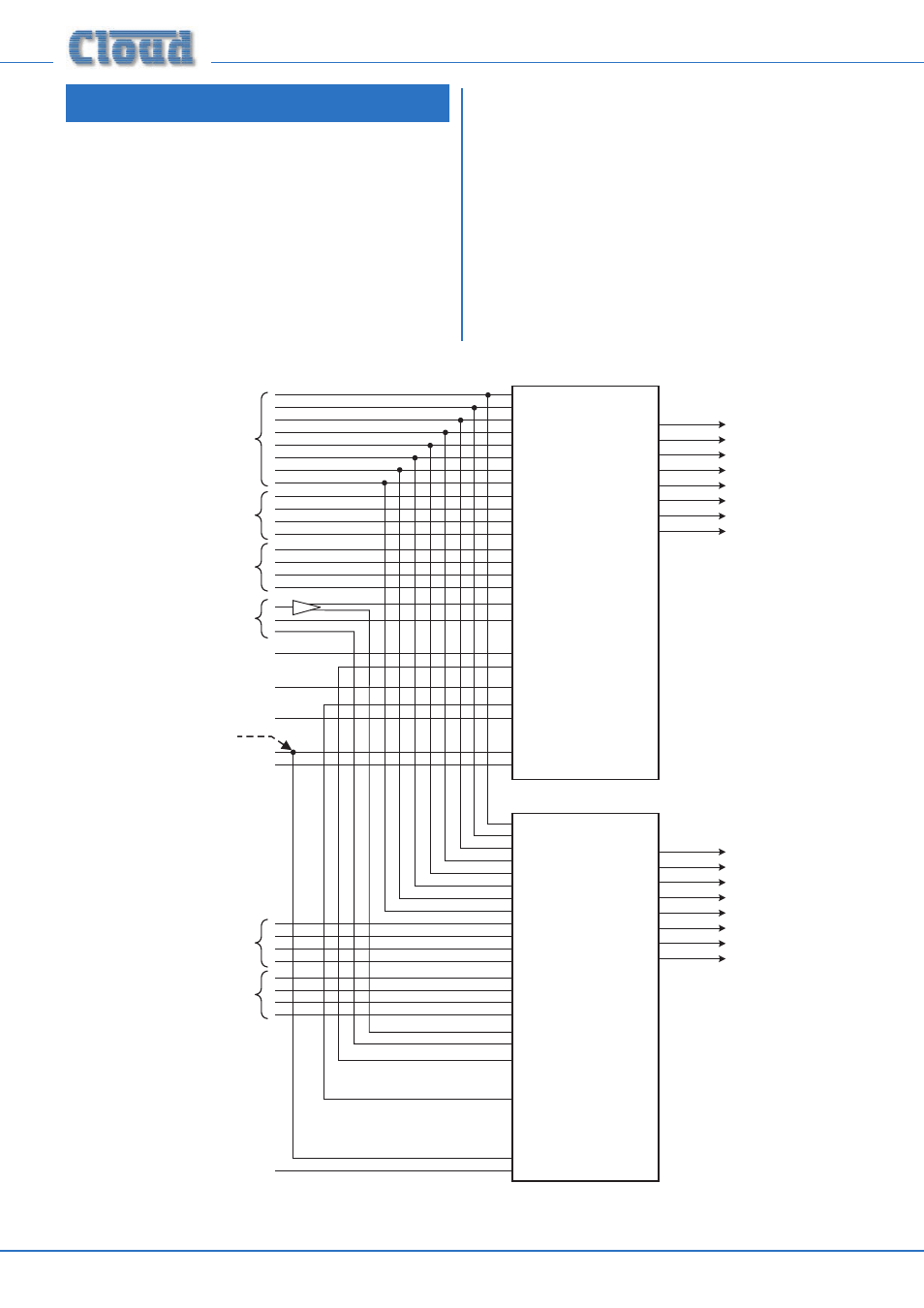
Larger systems – cascading DCM1s
If an installation requires more than eight Zones, multiple
DCM1s may be interconnected to provide a system with
a larger number of outputs. For example, two DCM1s will
provide 16 zones, three DCM1s 24 zones, and so on.
System Interconnections
In order to provide a transparent system which can be
operated with the same ease as one with a single DCM1,
interconnections between multiple DCM1s must follow a
few rules. The range of possibilities afforded by using multiple
DCM1s is extremely large, and each installation will be guided
by the user’s requirements and the building layout.
The example given is for a simple 16-zone system comprising
2 DCM1s, with a CDR-1 in each of the 16 zones. The block
diagram below shows how the various inputs are – or are
not – interconnected. All possible connections have been
depicted, though it is recognised that most systems will not
use all of a DCM1’s connectivity simultaneously.
DCM1 #1
INPUT 1
INPUT 6
INPUT 4
INPUT 8
INPUT 2
INPUT 7
INPUT 3
INPUT 5
CD
PM
MIC 1
MIC 4
MIC 2
MIC 3
PAGING MIC
PAGING ACCESS
ZONE 5
ZONE 3
ZONE 2
ZONE 6
ZONE 8
ZONE 4
ZONE 7
ZONE 1
EXT 1
EXT 4
EXT 3
EXT 2
IN
THRU
MUSIC MUTE
RS232
DCM1 #2
INPUT 1
INPUT 6
INPUT 4
INPUT 8
INPUT 2
INPUT 7
INPUT 3
INPUT 5
CDP
M
MIC 1
MIC 4
MIC 2
MIC 3
PAGING MIC
PAGING ACCESS
ZONE 5
ZONE 3
ZONE 2
ZONE 6
ZONE 8
ZONE 4
ZONE 7
ZONE 1
EXT 1
EXT 4
EXT 3
EXT 2
IN
THRU
MUSIC MUTE
RS232
ZONE 5
ZONE 3
ZONE 2
ZONE 6
ZONE 8
ZONE 4
ZONE 7
ZONE 1
ZONE 13
ZONE 11
ZONE 10
ZONE 14
ZONE 16
ZONE 12
ZONE 15
ZONE 9
See note
in text
MUSIC SOURCES
1 TO 8
REMOTE LINE
INPUTS IN ZONES
1 TO 8
REMOTE LINE
INPUTS IN ZONES
9 TO 16
REMOTE MIC
INPUTS IN ZONES
1 TO 8
REMOTE MIC
INPUTS IN ZONES
9 TO 16
FROM THIRD
PARTY PAGING
SYSTEM
FROM CDPM
CDR-1 NETWORK A
CDR-1 NETWORK B
RS232 A
RS232 B
SPLITTER
CDR-
1P
ORTS
1
2
1
2
PORT
AP
OR
TB
CDR-
1P
ORTS
1
2
1
2
PORT
AP
OR
TB
Two DCM1 Units forming a 16 Zone system