Hardware considerations, System connections, Power supply – Cloud Electronics DCM1 User Manual
Page 17: Music sources, Standard connection, Mono sources, Balanced sources, Additional balanced sources
DCM1 & DCM1e Installation and User Guide v1.0
17
Hardware considerations
The DCM1 is built in a 2U-high 19” rackmount enclosure.
It
is strongly recommended that the DCM1 is installed
in a 19” rack wherever possible. The DCM1 is approx.
160 mm deep, but 250 mm of rack depth should be available
to allow for rear connectors and cabling.
The DCM1 has low power consumption and there are
no thermal considerations other than ensuring that the
ventilation grilles (one on each side, one on the bottom panel)
are not obstructed once installed. Other equipment may be
installed above or below the DCM1 within this constraint.
The choice of location will be dictated by the specifics of the
system and building layout. It is recommended that wherever
possible, the DCM1 should be mounted in an equipment rack
along with as many of the music sources (CD players, music
servers, TV receiver boxes, etc.) and audio power amplifiers
(driving the zone loudspeakers) as practical.
When deciding the DCM1’s location, bear in mind that access
to it may be required, as there are some configuration settings
that may need to be changed - occasionally or frequently -
depending on the daily requirements of the building. This is
more likely to be the case with a DCM1 than a DCM1e, as
the latter allows many setting to be adjusted remotely from
an external device.
Power Supply
The DCM1 requires ±12 V DC, which is supplied by the
external DC Power Supply Unit (PSU) included with the unit.
This has a 1 m captive cable with a moulded 4-pin plug for
connection to the DCM1. The PSU is of the “Universal” type,
and will operate on any AC supply voltage from 100 to 240 V.
Wherever possible, mount the PSU in a safe location within
the equipment rack, securing both the DC cable and the IEC
mains lead with cable ties to avoid inadvertent disconnection.
System Connections
Music Sources
Connect the system’s various music sources to
LINE 1 to 8.
When allocating sources to inputs, bear in mind that if Cloud
LE-1 or BE-1 remote modules also form part of the system,
these can be connected to
LINE 1 to 4 only.
Standard connection:
All eight line inputs offer unbalanced connection for stereo
sources on a pair of standard phono sockets (RCA jacks).
The sensitivity range available should allow most standard
items of audio equipment such as CD players, PC-based music
servers, TV tuners, etc., to operate at a satisfactory level. Such
equipment will generally have stereo unbalanced outputs, and
as long as the source equipment is adjacent to the DCM1,
normal phono-phono leads can be used.
Mono sources:
If connecting a source with only a single mono output to
the DCM1, connect it to both the L and R sockets, using a
Y-splitter lead or similar.
Balanced sources:
LINE 8
is additionally provided with electronically-balanced
inputs, which may be used to connect source equipment with
balanced outputs. Balanced connection is always preferable to
unbalanced for situations involving long cable runs, and should
be used if one of the music sources is remote from the DCM1
(a DJ mixing system is a common example).
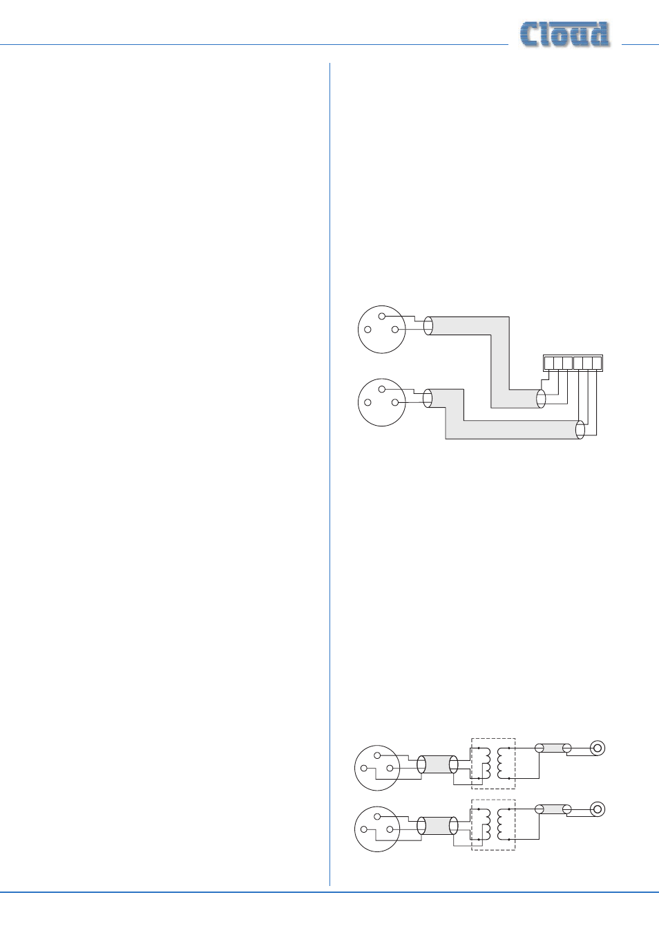
When connecting balanced sources to
LINE 8’s balanced
input connector, wire as shown below. Note that the cables’
screens are not connected at the source end.
1
2
3
LEFT
RIGHT
LEFT
RIGHT
1 2 3 1 2 3
+
+
-
-
+
+
-
-
SC
N
SC
N
pin 1 ground
pin 2 hot
pin 3 cold
Balanced outputs (XLRs):
DCM1 Balanced inputs
pin 1 ground
pin 2 cold
pin 3 hot
1
2
3
Do not connect music sources to both the balanced and
unbalanced connectors of LINE 8.
Additional balanced sources:
If it is necessary to connect more than one balanced source
to the DCM1, one of the unbalanced inputs 1 to 7 may be
used, but the advantages of balanced connection will be lost
unless a balancing transformer is connected between the
source and the unbalanced input. Suitable audio transformers,
which should have a ratio of 1:1, are readily available from
major audio component suppliers. The transformer(s) should
be mounted as close to the DCM1 as practical, and housed in
a screened enclosure if they are not individually screened. The
preferred connection method is shown below.
LEFT
+
-
SCN
Unbalanced
inputs
SCN
LEFT
+
-
SCN
Audio balancing transformers
RIGHT
+
-
SCN
Unbalanced
inputs
SCN
RIGHT
+
-
SCN
pin 1 ground
pin 2 hot
pin 3 cold
Balanced outputs (XLRs):
1
2
3
1
2
3