Cloud Electronics DCM1 User Manual
Page 21
DCM1 & DCM1e Installation and User Guide V1.0
21
Network Terminations
The Cat 5 wiring connecting the DCM1 and CDR-1s is
essentially a data network, and as such, must be correctly
terminated. Both the DCM1 and CDR-1 are provided with
means of setting their network terminations ON or OFF.
The rule governing terminations is:
•
Devices (DCM1 or CDR-1) at the
ends of a cable run
must have their terminations set ON.
•
All intermediate devices must have their terminations
set OFF.
•
If both connectors on the same DCM1
CDR-1 PORT
(either
PORT A or PORT B) are being used, the
DCM1 may be considered as an intermediate device,
and its termination should be set to OFF.
The correct termination setting is indicated for each device
in the three network examples illustrated on page 19 and
page 20. Note that in Example 1, the DCM1’s Ports A and B
are both in use, but only one connector is used on each. The
ports are thus at the ends of the chains, and their terminations
must therefore be set ON. In Example 2, all four ports are in
use, so the DCM1 is “mid-chain” with respect to both ports,
so both terminations should be set OFF.
There are two network terminations in the DCM1, one for
each port. These are set by internal jumpers J6 (Port A) and
J13 (Port B). See page 65 for details of jumper locations.
The port termination is ON when the jumper is in place.
Remove the jumper carefully, with a pair of long-nosed pliers,
to set the port termination OFF. (We suggest the jumper is
left on one of the two pins in case it is required in the future.)
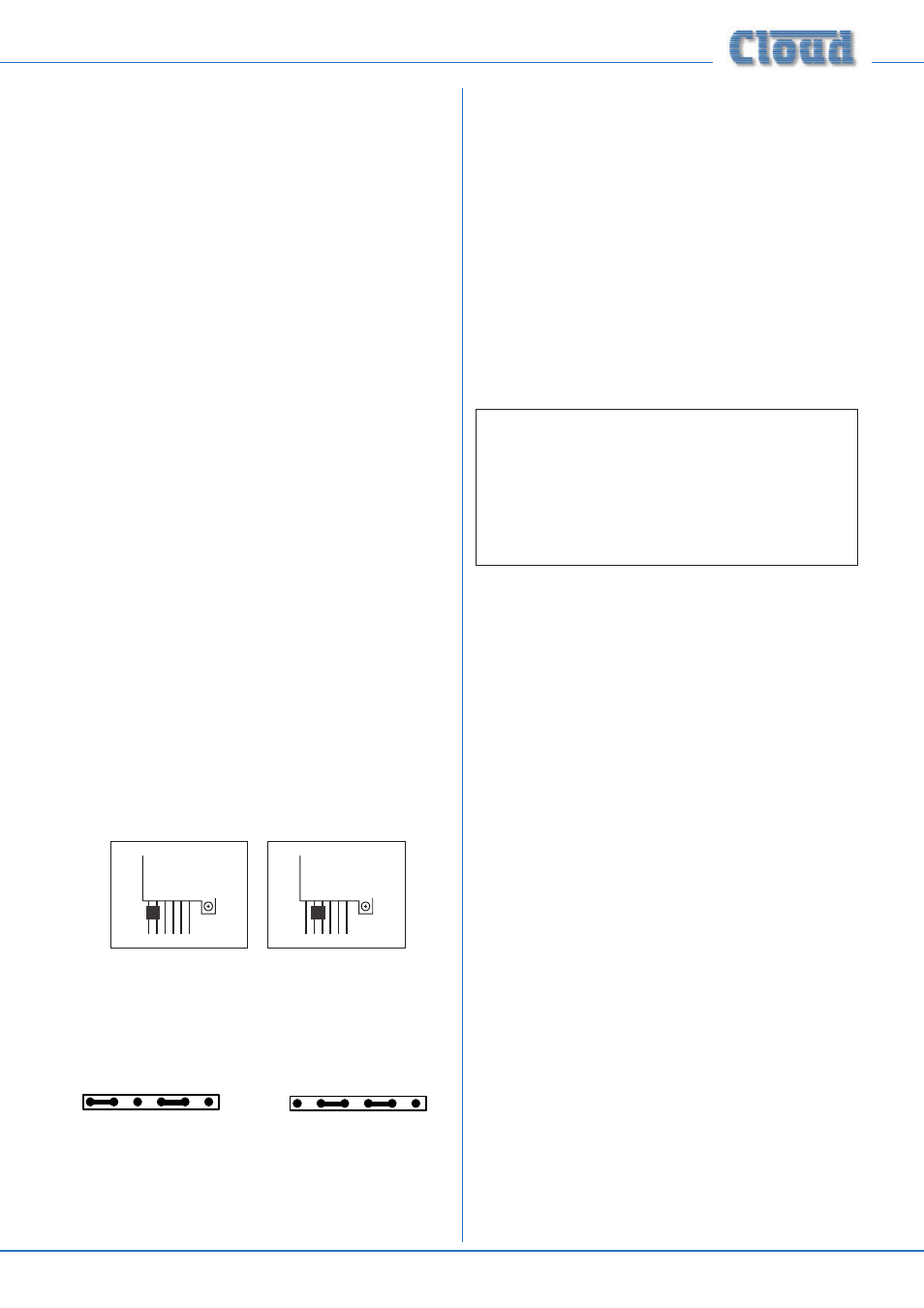
On the CDR-1 and CDR-1F, the network termination is set
by jumper J2. This has two possible positions, marked
MID
(termination OFF) and
END (termination ON).
J2
J1
MI
D
EN
D
ON
OF
F
J2
J1
MI
D
EN
D
ON
OF
F
Diagrams showing CDR-1 jumper settings for :
a) termination OFF (MID), b) termination ON (END).
Note Jumper J1 not shown.
MID
END
OFF
ON
MID
END
OFF
ON
Diagrams showing CDR-1F jumper settings for :
a) termination OFF (MID), b) termination ON (END).
Note Jumper J1 not shown.
Cable length and DC power considerations
As far as correct data communications are concerned,
the maximum recommended cable length of the
CDR-1 network is 1 km. This figure applies either to
the total cable run between the “farthest” CDR-1 and
the DCM1 if a single daisy-chain of CDR-1s has been
employed (see Network Diagram 1, page 19), or to the
total run between the most remote CDR-1s if the DCM1
is in the “middle” of the chain (i.e., multiple daisy-chains of
CDR-1s, see Network Diagram 2, page 19). Cable runs
longer than this may work satisfactorily, but this cannot be
guaranteed. The probability of correct operation is a function
of cable length, the number of CDR-1s daisy-chained, and how
many of them are at a distance from the DCM1 close to the
maximum cable length.
IMPORTANT: The 1 km limit referred to above ONLY
applies to the digital data carried by the Cat 5 cable; a
DCM1 will NOT successfully supply DC power over
this cable length. Systems with long cable runs and/
or several CDR-1s on the same run will need external
power supplies, whose location and system connection
will depend on the topology and cable lengths involved.
The DCM1 has sufficient capacity to power eight CDR-1s
and/or CDR-1Fs (i.e., nominally one plate per zone) via the
Cat 5 connections. However, in addition to the limitation
above, one or more external PSUs will be required if any of
the following apply:
•
If the system requires more than eight CDR-1s in total;
•
If the “first” CDR-1 on a daisy-chain is more than 250 m
cable run from the DCM1;
•
If several CDR-1s are in a “cluster” (i.e., close together
in cable run terms) on a single daisy-chain.
The DCM1’s power supply capability can be maximised by
using as many
CDR-1 PORT sockets as possible when
wiring CDR-1s.
As with data communication, the probability of satisfactory
operation is a function of DCM1-to-CDR-1 cable run, the
number of CDR-1s on each daisy-chain and the number of
CDR-1 PORT sockets used. If any CDR-1s in a system are
found to operate unreliably, it is likely that some will need
to be powered independently; as outlined above, this will
probably be the case with longer cable runs and/or several
CDR-1s on the same daisy-chain. The Cloud CPM-PSU is a
suitable external power supply, and should be connected to
the
EXT POWER socket in the rear of the CDR-1. Note
that any further CDR-1s connected to the
POWER OUT
connector will be powered by the external PSU.
If a third-party external PSU is to be used, it should be
rated at either 12 – 24 V DC or 9 – 17 V AC. Each CDR-1/
CDR-1F takes 50 mA at 12 V, so the current capability of any
PSU should also be checked. See page 69 for details of PSU
and current ratings.