System 3, Security – Cloud Electronics DCM1 User Manual
Page 13
DCM1 & DCM1e Installation and User Guide v1.0
13
System 3
EXTENSION 1
INPUT 6
INPUT 8
INPUT 7
INPUT 5
CDPM/PM
MIC 1
MIC 4
MIC 2
MIC 3
PAGING MIC
PAGING ACCESS
CDR-1
PORTS
1
2
3
4
ZONE 5
ZONE 3
ZONE 2
ZONE 6
ZONE 8
ZONE 4
ZONE 7
ZONE 1
AREA 1
AREA 2
AREA 3
AREA 4
AREA 5
AREA 6
CDR-1
CDR-1
CDR-1
CDR-1
CDR-1
CDR-1
PM PAGING
MIC
SECURITY
3RD. PARTY
PAGING
SYSTEM
MIC
CONTROL
LE-1
LE-1
EXTENSION 2
EXTENSION 3
EXTENSION 4
RADIO
TUNER
TV
MP3
PLAYER
COMPUTER
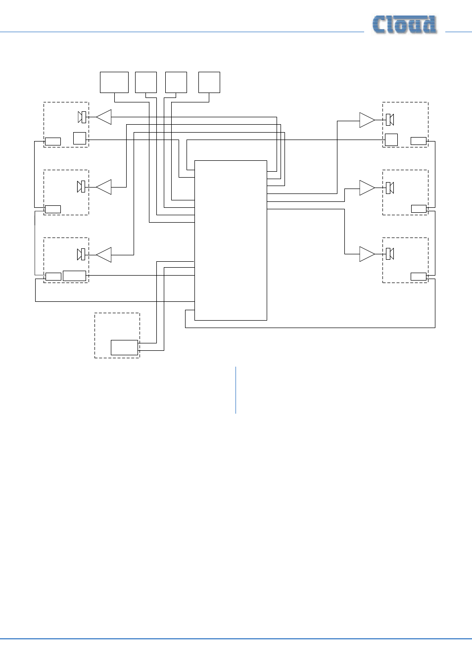
System 3 shows a system interfaced to two paging stations, a
PM (which might be located at the building’s reception desk)
and a separate third-party system, which might typically be in
a security office. Other points to note:
•
The CDR-1 remote control panels in each zone are
wired in two chains, to suit the building layout.
•
Two of the line inputs are from LE-1 remote line input
modules in two different zones. Other music sources
have, in this case, been connected to Inputs 5 to 8.