Description of rear panel – Cloud Electronics DCM1 User Manual
Page 15
DCM1 & DCM1e Installation and User Guide V1.0
15
15
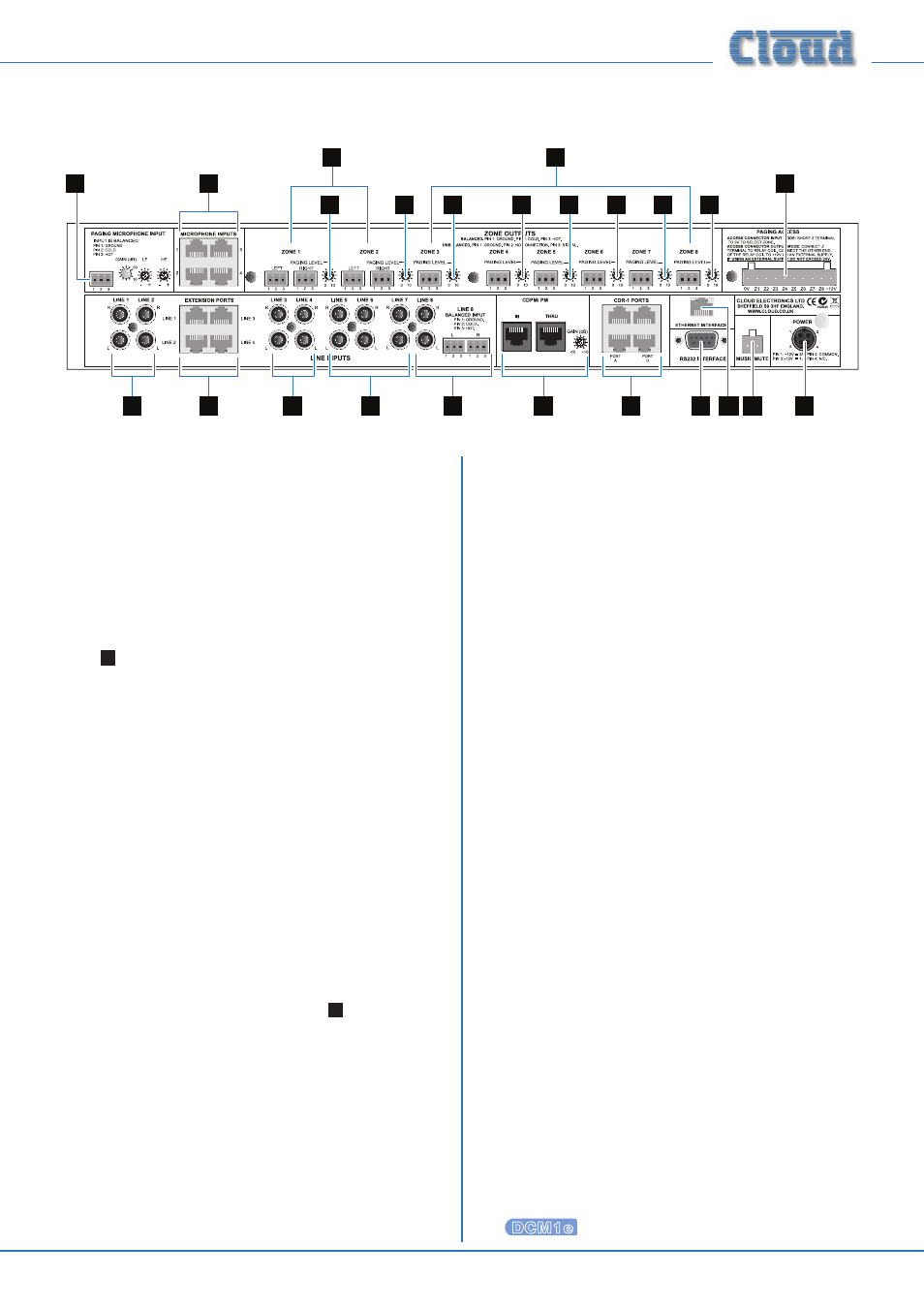
Description of rear panel
1
1
4
11
12
13
15
16
3
2
5
8
9
10
10
10
10
10
10
10
10
7
6
14
1.
Line 1 to 4: inputs for music sources 1 to 4, on phono
sockets (unbalanced).
2.
Extension Ports 1 to 4: These are alternative input
connectors for Line Inputs 1 to 4. If Cloud remote line
input modules (LE-1 or BE-1) are being used, they should
be connected here via screened Cat 5 cable and shielded
RJ45 connectors. These ports each provide a stereo
pair of electronically-balanced inputs, together with DC
power for the active circuitry in the remote module.
Do not connect a music source to the phono sockets
(
1
above) of a Line Input when its Extension Port is
connected to a remote input module.
3.
Line 5 to 7: inputs for music sources 5 to 7, on phonos
only.
4.
Line 8: Input 8 is available both as unbalanced on phonos
and electronically-balanced on 2 x 3-pin 3.5 mm-pitch
screw-terminal connectors. The balanced input allows
connection of professional audio equipment such as
mixing consoles, DJ desks, etc.
5.
Microphone Inputs 1 to 4: four shielded RJ45 sockets
for the connection of Cloud ME-1 microphone remote
input modules. Connection should be via screened
Cat 5 cable. These inputs are balanced, and the connectors
additionally provide DC power for the active circuitry in
the input modules.
6.
Paging microphone input: balanced input for the
connection of an external paging microphone. This input
is enabled via the access connector
7
. Adjacent to the
3-pin 3.5 mm-pitch screw-terminal connector are preset
controls for mic gain and HF/LF EQ. Phantom power is
available at this input (enabled by internal jumper).
7.
Paging Access connector: 10-pin 5 mm-pitch screw-
terminal connector providing several functions. If the
DCM1 is being used with a third-party paging system,
this connector provides contact-closure selection of the
zone(s) to be paged. If a Cloud PM Series is the only
type of paging system being used, the connector can be
used as an output port, the 8 pins becoming per-zone
open-collector outputs which can be used (typically)
for external level restoration. If the connector is not
required for paging access, it can be configured as a GPIO
port (with any combination of inputs and outputs), and
used in conjunction with the RS-232 port to respond to
serial commands (GPO) or report input status (GPI). 0 V
and +12 V are also available on the connector. See page
33 for more information.
8.
Zone Outputs 1 and 2: electronically-balanced outputs
on 3-pin 3.5 mm-pitch screw-terminal connectors. Zone
Outputs 1 & 2 are stereo; separate L and R connectors
are provided. Stereo music sources routed to Zones 1
and 2 will remain in stereo. Either Zone Output can be
reconfigured as mono via the menu system.
9.
Zone Outputs 3 to 8: as Zones 1 and 2, but mono only,
with a single connector. These zones will receive a mono
L+R sum of stereo inputs routed to them.
10. Paging level controls: each Zone output has an
adjacent preset control which sets the volume of the
paging mic (either from PM or third-party systems) in
that zone.
11. CDPM/PM ports: two RJ45 sockets, IN and THRU.
IN is for the connection of Cloud PM Series (or CDPM
Series) paging microphones; THRU is used when a system
employs multiple DCM1s. DC power, zone selection data
and the paging microphone signal are all catered for on
the IN socket. The adjacent preset control adjusts the
PM microphone level.
12. CDR-1 Ports: four RJ45 ports for connection of
CDR-1 (or CDR-1F) remote control plates. Plates may
be daisy-chained, and the installer may use one or more
of the four ports for individual or daisy-chained plates as
the building layout dictates.
13. RS232 serial interface: a 9-pin female Dsub
connector providing a bi-directional RS-232
interface. This has several functions: it permits
control of the DCM1’s primary functions from an
external system and can be used in conjunction
with the Paging Access connector in GPIO mode.
On the DCM1e only, it can transmit serial