Engineer mode, Installer mode – Cloud Electronics DCM1 User Manual
Page 48
DCM1 & DCM1e Installation and User Guide V1.0
48
The CDR-1 will change to the adjustment display shown at ii)
above after approx. 10 seconds, or immediately if either the
+ or – buttons are pressed. The i and h buttons can now be
used to scroll through the inputs available to the zone. Only
those inputs which have been enabled in the DCM1 menu
system at ROUTING > Input Enable will be displayed. The
+ and – buttons adjust the volume.
This sequence is modified if the Zone has been defined as a
member of a Group. If so, the next press of ZONE after the
panel “wakes-up” displays the Engineer Mode Enter Key
screen. This gives the user the option of entering the key, after
which the display will show the Group Select screen.
Enter Key
Group Select
Group 1
keys to select Zone or Group(s)
and
The
+ and – keys may now be used to change enable or
disable any Groups of which the Zone has been defined as
a member. If the Zone is only a member of one Group, the
lower row of the display will toggle between Zone n and
Group m
where n and m are the Zone and Group numbers
respectively. If the Zone belongs to more than one Group, the
additional Groups will be displayed in turn; pressing ZONE
when a Group is displayed will enable that Group; pressing
ZONE when the Zone is displayed will disable a Group and
return to normal operation.
Engineer Mode
The CDR-1 may be placed in Engineer Mode to allow EQ
adjustment to be performed from within the zone itself.
Engineer Mode is fully described on page 35.
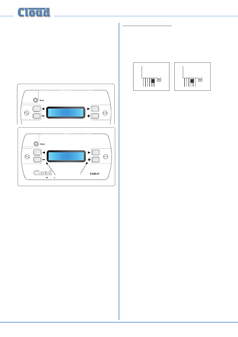
Installer Mode
Installation of a CDR-1 necessitates the activation of a further
mode, Installer Mode, to allow some additional parameters
to be set, including zone assignment. (NOTE: CDR-1 Installer
Mode, described here, is not to be confused with DCM1
Installer Mode.)
To activate Installer Mode:
If the CDR-1 has already been installed, remove it from its back
box and disconnect the power supply, either by unplugging the
POWER IN RJ45 connector if the CDR-1 is being powered
from elsewhere in the system, or by unplugging the local PSU
if it is being powered locally. Move the jumper J1 as shown
below.
J2
J1
MI
D
EN
D
ON
OF
F
J2
J1
MI
D
EN
D
ON
OF
F
Normal Mode
Installer Mode
Reconnect the CDR-1 to its power supply, and the display
will change to the first of the four menu functions available in
Installer Mode. Pressing ZONE steps through each function in
turn (in the same manner as the NEXT FUNCTION button
in the DCM1’s menu system). The two User Mode screens
are also presented before the menu loops around.
The i, h ,
+ and – buttons are used to adjust the parameters
in each function.
Note that the display time-out is disabled in Installer Mode.
Remember to remove the power from the CDR-1 and put J1
back to its “normal” setting after configuration is complete.