System capabilities, Music sources and routing, Microphone inputs – Cloud Electronics DCM1 User Manual
Page 9: Paging mic facilities, Zone outputs, Zone groups, Priority and logic, Remote control, Input 8 also available as a balanced input, Any music source may be routed to any zone
DCM1 & DCM1e Installation and User Guide V1.0
9
System Capabilities
SPE
ZONES 1 AND 2 ARE STEREO
ZONES 3...8 ARE MONO
+
MIC PRIORITY
MICROPHONE INPUTS
EQ
VCA
ATTENUATOR
LINE 8
LINE 7
LINE 6
LINE 5
LINE 4
LINE 3
L
R
LINE 2
LINE 1
EXTENSION PORTS
1
2
3
+
+
LINE 8
BALANCED
R
L
LINE 1
LINE 2
LINE 3
LINE 4
MIC 1
MIC 2
MIC 3
MIC 4
GAIN
SOURCE SELECT LOGIC
CDR-1 PORTS
EQ CONTROL BY CDR-1 IS ONLY
AVAILABLE IN ENGINEER MODE
LINE PRIORITY
LOGIC
GAIN IS APPLIED
ACCORDING TO
SOURCE SELECTED
+
+
EQ
PAGING ACCESS
LOGIC
PAGING
MICROPHONE
INPUT
CDPM IN
CDPM THRU
+
PAGING ACCESS
Z2
Z1
Z3 Z4 Z5 Z6 Z7 Z8 0V
+12V
PORT
A
PORT
A
PORT
B
PORT
B
ONLY RIGHT STEREO SIGNAL
SHOWN FOR CLARITY.
ZONES 3...8. SIGNALS ARE SUMMED
TO MONO BEFORE SOURCE SELECT.
1
2
3
1
2
3
1
2
3
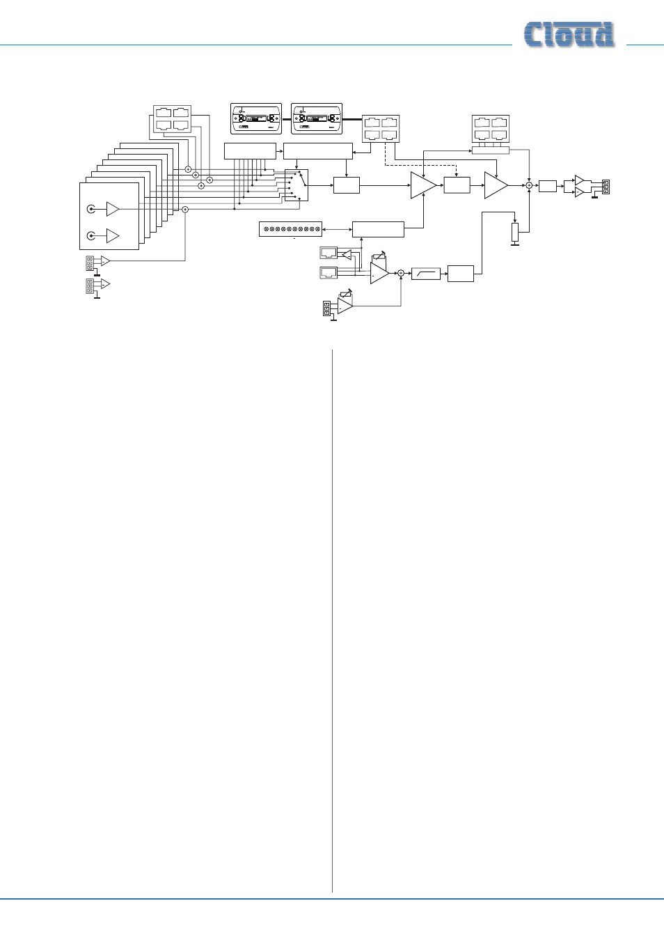
The simplified block diagram above illustrates the basic signal
architecture of the DCM1. Only the routing and logic for one
zone output is shown.
The main system and interfacing capabilities of the DCM1 are
listed below:
Music sources and routing
•
Provision for eight music sources. Inputs are stereo, line-
level and unbalanced
•
Input 8 also available as a balanced input
•
Inputs 1 to 4 may be fed from LE-1 or BE-1 input
modules (see above), which have a balanced connection
via dedicated input sockets
•
Any music source may be routed to any zone
•
Inputs available for selection may be defined, per-zone
Microphone inputs
•
Provision for four ME-1 mic input modules, each of
which can accept two microphones (except the single-
input ME-1M).
•
Each mic input assignable to any zone in any
combination
Paging mic facilities
•
RJ45 digital interface for PM/CDPM Series paging
microphones
•
Additional balanced input for third-party paging mic
•
Per-zone contact closure routing for third-party mic
•
Both PM and third-party systems may be used together;
independent gain controls.
•
HF/LF EQ adjustment of paging signal
•
Paging level independently adjustable per-zone
Zone Outputs
•
Eight balanced line level zone outputs
•
Zones 1 & 2 are stereo, 3 to 8 are mono
Zone Groups
•
Zones may be assigned in any combination to four Groups
•
Groups can be enabled/disabled by user as required
•
Groups have same source selection functions as zones
Priority and Logic
•
Any music source may be assigned as priority line input,
per-zone/group. If enabled, a signal at the priority input
overrides the source selection in the zone/group
•
Priority music source may be a source normally
unavailable to a zone
•
One or more priority mic inputs may be similarly
defined; an active mic signal causes the music level to
reduce (“ducking”)
•
During Paging, music ducking may be triggered by the
paging signal or zone selection; it can also be disabled;
these options are selectable per-zone/group
•
Independently adjustable hold and release times for all
priority types, plus music attenuation (ducking) level for
mic and paging priorities
Remote Control
•
Optional CDR-1 dedicated remote control for DCM1
available separately
•
Up to 100 CDR-1s may be connected to the four
CDR-1 Ports, using standard Cat 5 UTP cable
•
CDR-1s can be daisy-chained and/or wired directly to
the CDR-1 Ports as cabling convenience dictates
•
Multiple CDR-1s per-zone permitted
•
CDR-1 provides local (in-zone) user control of source
selection and level control and key-protected EQ
adjustment