Connecting paging systems, Be-1 me-1 le-1, Cloud pm paging microphones – Cloud Electronics DCM1 User Manual
Page 23
DCM1 & DCM1e Installation and User Guide v1.0
23
Connections and wiring
Cat 5 cables used to interconnect remote input modules
carry low-level audio. To minimise noise and interference
from outside sources, only screened Cat 5 should be used. Only
use shielded RJ45 plugs when wiring this part of the system,
bonding the foil screen of the cable to the metal screening
can of the plug.
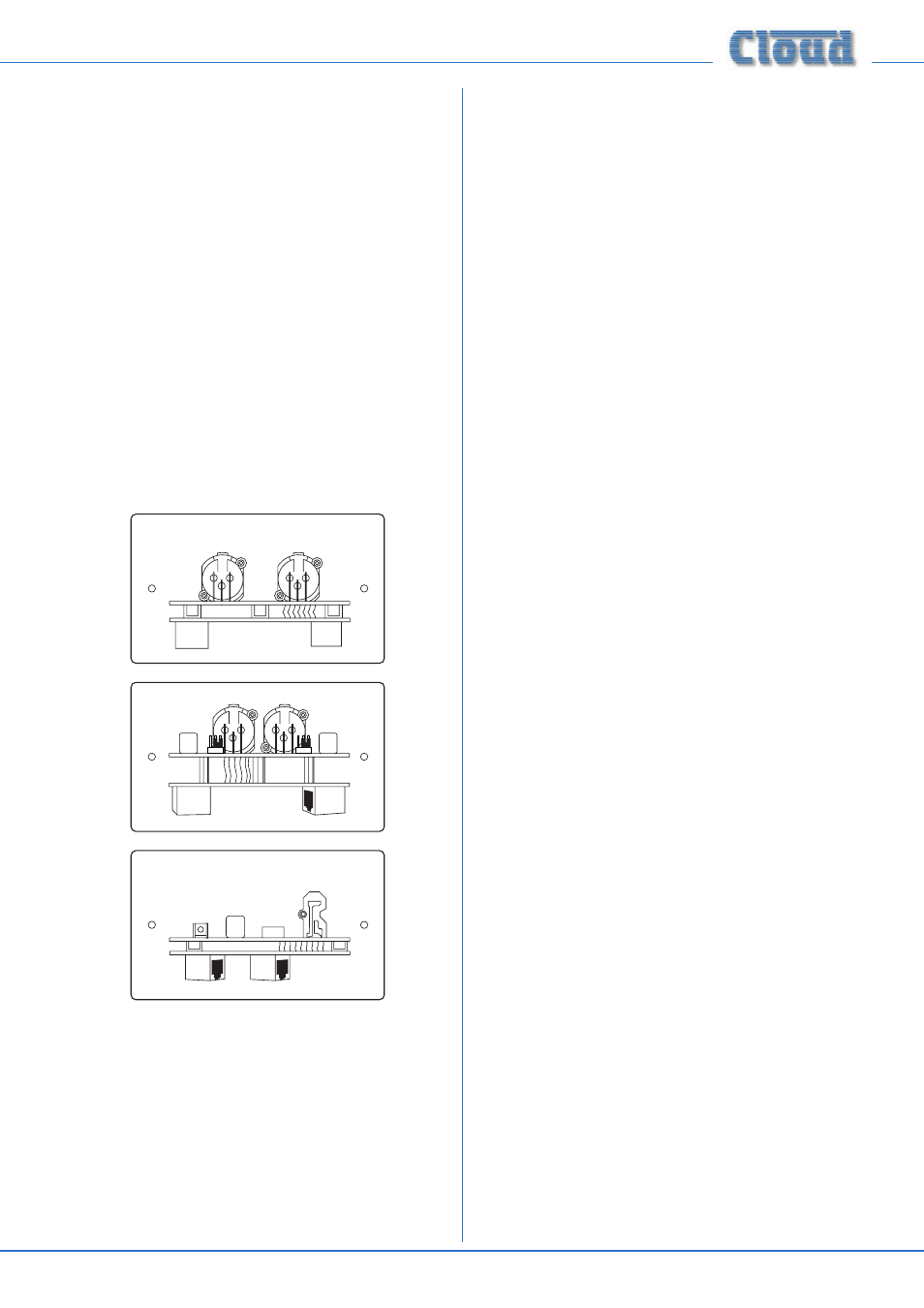
ME-1 mic input modules should be connected to the RJ45
connectors labelled MICROPHONE INPUTS on the DCM1.
LE-1 line input modules and BE-1 balanced line input modules
should be connected to the RJ45 connectors labelled
EXTENSION PORTS
on the DCM1. Do not connect any
music sources to the phono sockets corresponding to the
Extension Ports being used.
The remote modules all have two RJ45 sockets, labelled
OUTPUT
and LINK
. The “first” module in a daisy-chain
wiring system should be connected to the DCM1 using its
OUTPUT
socket. The LINK socket on this module should be
connected to the OUTPUT of the next module in the chain,
and so on until the last module in the chain.
LINK
OUTPUT
BE-1
ME-1
LE-1
OUTPUT
LINK
OUTPUT
LINK
Refer to Installation Guide for the Module
Note that the single Cat 5 interconnection provides DC
power as well as audio. A full pin allocation of the Microphone
Inputs and Extension Ports can be found in the Appendix at
the end of this Guide.
The DC power consumption of the active circuitry is quite
low, and no PSU capacity problems should be experienced in
the vast majority of installations. Refer to page 69 for PSU
and current ratings.
Connecting Paging systems
Cloud PM Paging Microphones
The DCM1 fully supports the Cloud Paging Interface Buss
implemented across the Cloud PM range. (The Cloud Paging
Interface Buss is also used by the earlier Cloud CDPM paging
microphone range.)
Connections and wiring
The DCM1 is equipped with two RJ45 sockets for connection
of Cloud PM Series paging microphones. The sockets,
marked
CDPM/PM, are labelled IN and THRU. PM paging
microphones are similarly equipped with two RJ45 sockets,
labelled
IN and OUT.
If the system being installed includes one microphone, its
OUT socket should be connected to the IN socket on the
DCM1.
If the system requires more than one microphone, the
additional microphones should be “daisy-chained” together.
For example, two microphones would be wired by connecting
the
OUT socket of one to the IN socket on the DCM1
as above, and then connecting the
OUT socket of the next
microphone to the
IN socket of the first.
The diagram below illustrates the various methods of
connection. Note that the third example illustrates the
method of interfacing a PM16 to two DCM1s. In this case,
the
CDPM/PM THRU connector on the first DCM1 is
connected to the
IN on the second, and the PM Zone Offset
of the second would be set to +8. This would allow it to
correctly interpret commands from paging buttons 9-16 on
the PM16. See page 34
for full details of how to set PM
Zone Offset.
NOTE: The CDPM/PM THRU connector is only intended
for connection of additional DCM1 units, not for additional
PM paging microphones.