Music mute, Adjusting paging levels, Paging access connector – Cloud Electronics DCM1 User Manual
Page 26
DCM1 & DCM1e Installation and User Guide v1.0
26
Adjusting paging levels
Separate controls are available at the rear panel for setting
microphone sensitivity and the paging level sent to each Zone.
Full details on adjusting these can be found at page 46.
Paging Access Connector
The
PAGING ACCESS connector is used to activate the
paging microphone and to select the zone(s) to which it is to
be routed. It performs this function by default, though it can
be re-defined in the menu system to provide per-zone control
outputs when used with Cloud PM paging microphones (see
page 24). (Should a system require the use of both PM
and third-party paging systems, control outputs will not be
available if the connector is to be used in its “input” mode.)
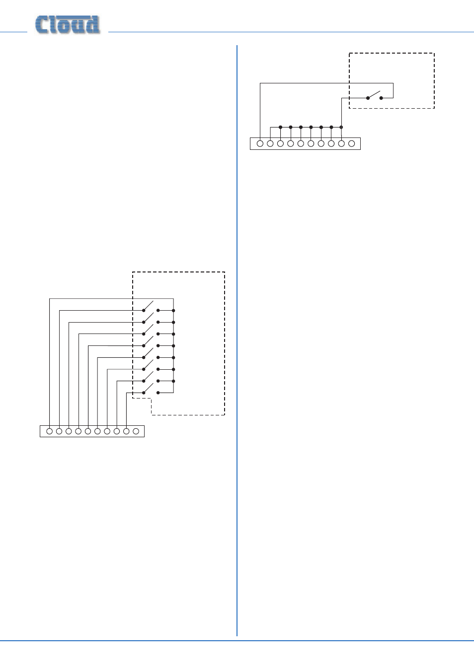
Zone activation occurs when one of the “zone active” pins
(2 - 9) is shorted to 0 V (available on pin 1). Third-party paging
systems providing per-zone contact-closure on zone selection
can thus be easily interfaced by wiring the external unit to the
PAGING ACCESS connector as shown below:
PAGING ACCESS CONNECTOR
+12v
1
0v
8
6
5
4
3
2
7
PAGE ZONE 1
PAGE ZONE 8
PAGE ZONE 7
PAGE ZONE 6
PAGE ZONE 5
PAGE ZONE 4
PAGE ZONE 3
PAGE ZONE 2
3RD-PARTY
PAGING SYSTEM
The pinout is the same as that given in page 24. Multicore
control cable should be used for the interconnection.
PAGING ACCESS CONNECTOR
+12v
1
0v
8
6
5
4
3
2
7
3RD-PARTY
PAGING SYSTEM
Some third-party paging systems have a single “page-all”
command output, which activates all zones in use. In this case,
use the wiring scheme shown above.
Visual indication that paging is taking place is given by the
Paging Access LEDs on the front panel. The LED(s) illuminate
to confirm the Zones being paged.
Music Mute
External muting of music is available at the
MUSIC MUTE
connector. National or Local Authority regulations governing
such systems may require that normal programme material
(i.e., music) should be muted in an emergency, to ensure that
any emergency messages are clearly audible.
The
MUSIC MUTE input is on a 2-pin screw terminal
connector. It should be connected to the appropriate alarm
output on whichever building management system registers
the alarm (typically the Fire System). The alarm output must
be volt-free; if no such output is available, an intermediate
relay or other isolation device must be installed between the
alarm output and the Music Mute input.
The Mute input can be programmed to operate on either
normally open (N/O) or normally closed (N/C) contacts via
the menu system (see page 45). The factory default setting
is N/O, thus requiring a short-circuit to be applied across the
two pins of the connector for muting to occur.
Visual indication of muting being activated is given by the
MUSIC MUTE LED on the front panel.
If the audio system itself is to be used to provide voice alarm
and/or evacuation messages, the DCM1 can be programmed
to not mute one particular line input when Music Mute is
made active. This input can be permanently connected to a
sound store or emergency evacuation microphone, so that
when activated, all inputs will be muted except the emergency
source. If this facility is being used, care should be taken to
ensure the emergency source is not made
available to any
zones in normal operation.