Serial control, Abridged command set, Pinout – Cloud Electronics DCM1 User Manual
Page 66: Port parameters
DCM1 & DCM1e Installation and User Guide v1.0
66
Serial Control
The DCM1 is equipped with a bi-directional RS-232 serial
interface.
As a receiver, the interface permits external control of almost
every DCM1 function, parameter and setting. The DCM1
appears as a DCE (Data Communications Equipment) device
to controlling equipment.
The DCM1e is additionally able to receive the same serial
commands in the form of TCP/IP data via the
ETHERNET
INTERFACE connector.
NOTE: A future firmware release for the DCM1e
will permit the RS-232 interface to be programmed
to transmit serial data to external equipment, thus
additionally acting as an Ethernet to RS-232 bridge for
equipment which does not have Ethernet capability.
The full RS-232 protocol is beyond the scope of this manual,
but can be downloaded from
www.cloud.co.uk
.
This section provides only details of the port parameters and
an abridged serial command list, which comprises the normal
User controls.
Pinout
The rear panel
RS232 INTERFACE connector is a D9F.
The pinout is shown in the table:
PIN
FUNCTION
1
n/u
2
Data receive
3
Data transmit
4
DTR
5
0v
6
DSR
7
RTS
8
CTS
9
n/u
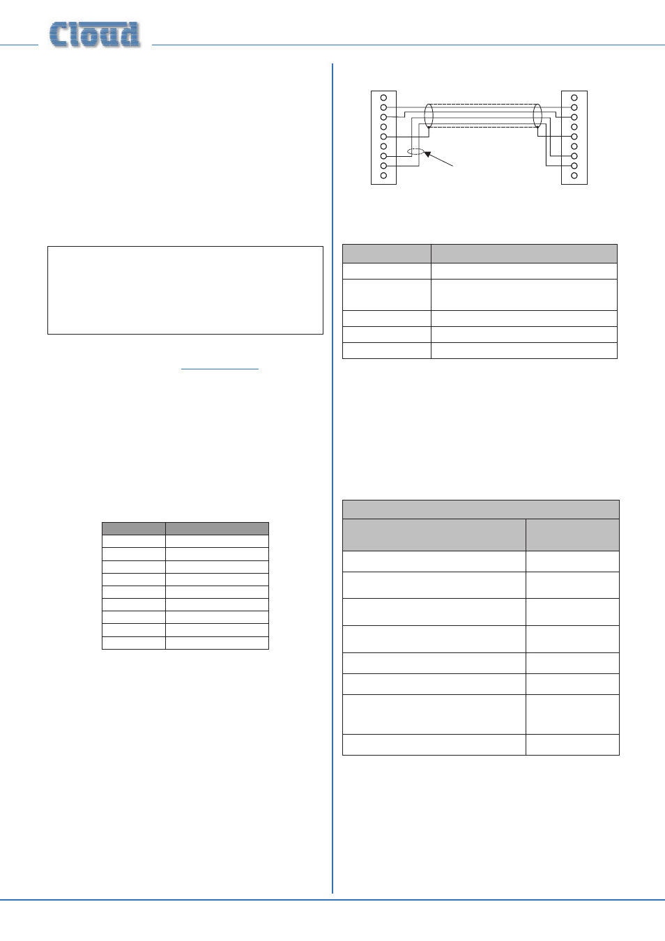
Not all control systems interpret “Tx” and “Rx” the same
way, and the installer should check whether pins 2 and 3 (and
7 and 8 if used) should be “crossed” within the cable. The
installer should also check whether the control system being
used requires RS-232 flow control to be implemented, and
if so, whether hardware control or software control is used.
Hardware flow control (sometimes called RTS/CTS) requires
pins 7 and 8 (at the DCM1 end) to be connected.
CONTROLLER
1
9
8
7
6
5
4
3
2
DCM1
Tx
Tx
Rx
Rx
CTS
CTS
RTS
RTS
Connect if hardware
flow control is
required
Port parameters
PARAMETER
VALUE/SETTING
Data type:
RS-232C serial
Data speed
300/1200/2400/4800/9600/19200 baud,
software-selectable
Word length
8 bits
Parity
None
Stop bits
One
Abridged command set
The commands listed in the table below are the equivalent of
the operating controls available in User Mode. For all other
commands, data requests and responses, please refer to the
DCM1’s full RS-232 protocol document.
GENERAL FORMAT
FUNCTION
COMMAND
(ASCII)
Route Input x to Zone y
<Zy.MU,Sx/>
Set audio level in Zone y to -m dB
<Zy.MU,Lm/>
Reduce audio level in Zone y by p dB
<Zy.MU,LDp/>
Increase audio level in Zone y by q dB
<Zy.MU,LUq/>
Enable Group z
<Gz,E/>
Disable Group z
<Gz,D/>
Enable paging to Zone y
(see Example 4)
<PM,PAy/>
Release paging
<PM,PR/>