System menu, Cdr zone setup – Cloud Electronics DCM1 User Manual
Page 35
DCM1 & DCM1e Installation and User Guide v1.0
35
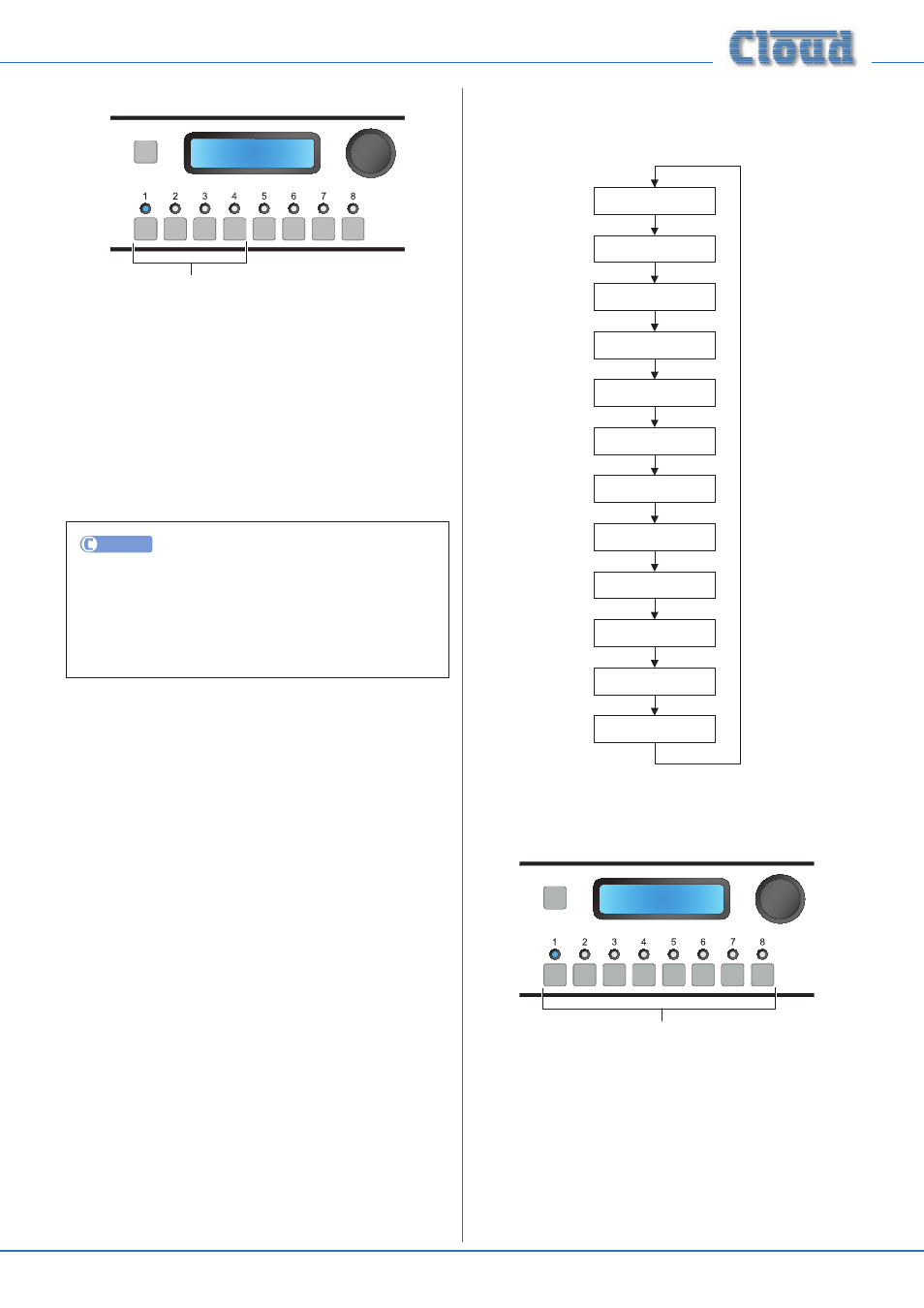
Mic Gate Enable
SELECT INPUT
Mic Gate Enable
Numeric buttons enable/disable gates
The ME-1 remote input module incorporates a noise gate
to reject unwanted background noise when the microphone
connected at the module is not in use. The Mic Gate Enable
menu function allows the noise gate to be switched on or
off. The first four numeric buttons correspond to the four
MICROPHONE INPUTS on the rear panel; the default
setting is for the noise gates to be active, and this is indicated
by the LEDs being illuminated.
The rotary control is not used in this function.
UTILITY
Mic Gate Enable may be configured by clicking the
SYSTEM tab, and then clicking in the appropriate Mic
checkbox(es) in the Mic Gates area. Click Send
System
to transmit the new setting.
System Menu
CDR Zone Setup
Zone 1
Stereo X
Edit Input Label
Input 1
Edit Zone Label
Zone 1
Edit Group Label
Group 1
Set Key
1234
RS232 Baud Rate
9600
RS232 Flow
No Flow
Power Up Mode
Factory
Save Defaults
X
Update Firmware
X
Reset Mixer
CDR Zone Setup
SELECT INPUT
CDR Zone Setup
Numeric buttons select Zone
The
CDR Zone Setup menu function lets the operator put
the CDR-1s in a system into
Engineer Mode. In this mode,
per-Zone output EQ can be adjusted locally, in the zone itself.
This permits much faster and easier optimisation of the sound
as the adjustment is made from the CDR-1(s) rather than
from the DCM1.
The eight numeric buttons correspond to the eight Zones;
select the Zone(s) where EQ is to be adjusted by pressing
the appropriate key(s). The default is for EQ Setup Mode to