Zone outputs, Standard connection – Cloud Electronics DCM1 User Manual
Page 18
DCM1 & DCM1e Installation and User Guide V1.0
18
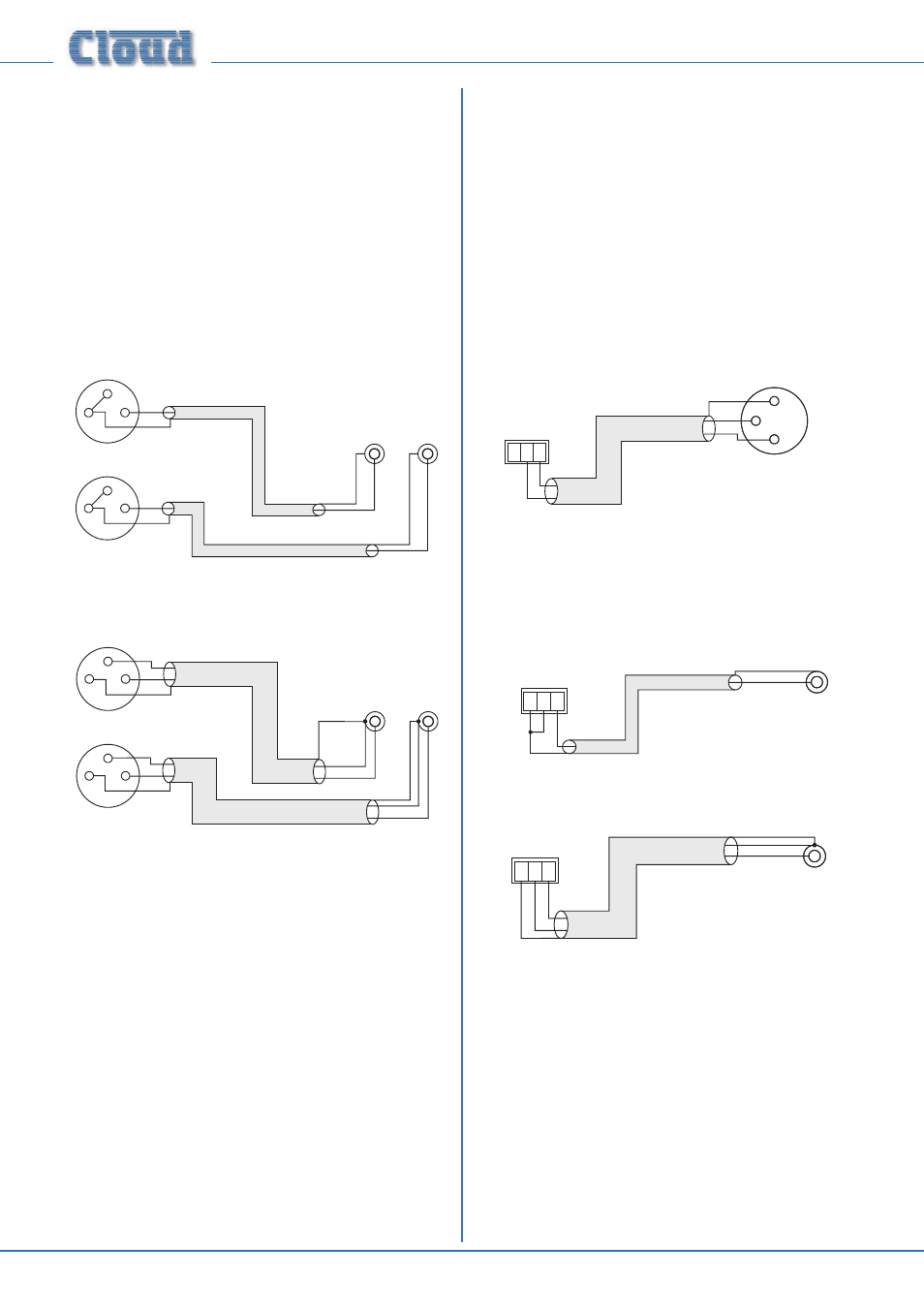
If transformers are not available, a balanced source may feed
an unbalanced input directly as long as care is taken over how
the connections are made. A variety of design techniques are
in use to implement balanced outputs in audio equipment,
and some designs require different wiring protocols to others.
Installers are advised to check the manuals with each item
for guidance on how the outputs should be connected to an
unbalanced input.
However, the wiring methods shown below will work in a
large number of cases. If hum or other distortion is found to
result, try disconnecting the ‘cold’ leg of the balanced output
(pin 3 on XLRs).
1
2
3
Unbalanced
inputs
LEFT
RIGHT
+
+
SCN
SCN
+
+
SCN
SCN
When using single-core cable,
join ‘cold’ to screen at the
source
LEFT
RIGHT
pin 1 ground
pin 2 hot
pin 3 cold
Balanced outputs (XLRs):
1
2
3
Unbalanced
inputs
LEFT
RIGHT
+
+
-
-
SCN
SCN
+
+
-
-
SCN
SCN
When using twin-and-screen
cable, join ‘cold’ to screen at
DCM1 end
LEFT
RIGHT
pin 1 ground
pin 2 hot
pin 3 cold
Balanced outputs (XLRs):
1
2
3
1
2
3
Always avoid using pre-made leads of an unnecessary length.
An alternative method of providing additional balanced
sources is to use BE-1 remote input modules connected
to
EXTENSION PORTS 1 to 4; these could be installed
adjacent to the DCM1 in such a situation.
Zone Outputs
Connect the inputs of the power amplifiers feeding the
loudspeakers for each zone to ZONE 1 to 8. Note that zone
outputs 1 and 2 are stereo; if only one set of speakers are
being used in these zones, they may be connected to either
connector.
Standard connection:
All eight outputs provide balanced connection for wiring to
professional/industrial power amplifiers with balanced inputs
(typically on XLRs). In this case, wire as the diagram below.
Note that the cables’ screens are not connected at the
source end.
1 2 3
+
-
+
-
1
2
3
SCN
pin 1 ground
pin 2 cold
pin 3 hot
pin 1 ground
pin 2 hot
pin 3 cold
DCM1 Balanced output:
Balanced input (e.g. XLR):
Unbalanced inputs:
If audio amplifiers with only unbalanced inputs are being used
(e.g., hi-fi amplifiers), the following wiring should be adopted:
1 2 3
+
+
SCN
SCN
pin 1 ground
pin 2 cold
pin 3 hot
DCM1 Balanced output:
Unbalanced input
(e.g. phono)
When using single-core
cable, join 'cold' to screen
at the DCM1
1 2 3
+
-
+
-
SCN
SCN
pin 1 ground
pin 2 cold
pin 3 hot
DCM1 Balanced output:
Unbalanced input
(e.g. phono)
When using twin-and-screen
cable, join 'cold' to screen
at the amplifier end
Always avoid using pre-made leads of an unnecessary length.