Examples – Cloud Electronics DCM1 User Manual
Page 67
DCM1 & DCM1e Installation and User Guide v1.0
67
Examples:
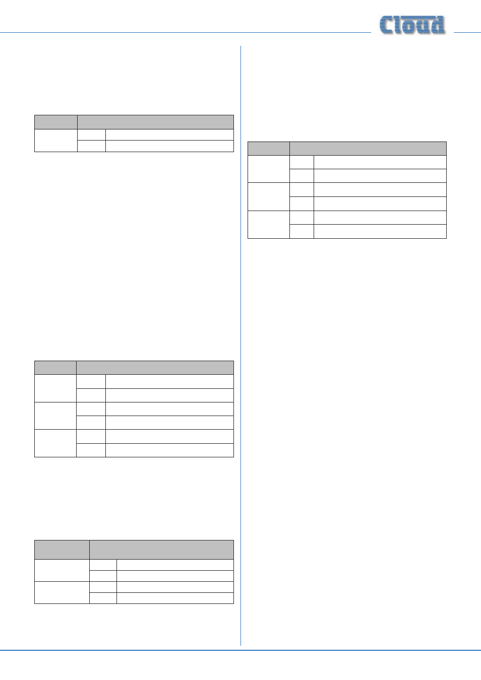
1. Input Selection:
The values of x and y in the general format are the Input No.
(1 to 8) and the Zone No. (1 to 8) respectively.
EXAMPLE
COMMAND
Select Input
3 in Zone 6
ASCII
<Z6.MU,S3/>
HEX
3C 5A 36 2E 4D 55 2C 53 33 2F 3E
2. Zone Levels:
Levels can either be set to an absolute value (in dBs), or
increased/decreased by a specified number of dBs.
For absolute levels, the number of dBs corresponds to
attenuation rather than gain, thus 0 dB is maximum level and
at -62 dB the zone is muted. The values of y and m in the
general format are the Zone No. (1 to 8) and the attenuation
level in dBs (0 to 62) respectively.
To alter the Zone level by a specified amount, the additional
ASCII characters ‘U’ (up) or ‘D’ (down) are added to the
string. The values of y, p and q in the general format are the
Zone No. (1 to 8), the level increase in dBs (0 to 62), or
the level decrease in dBs (0 to 62) respectively. A command
to increment the level by a number of dBs greater than the
current attenuation will set the level to maximum. Similarly, a
command to decrement the level by a number of dBs greater
than (62 minus the current attenuation) will mute the Zone
output.
EXAMPLE
COMMAND
Set level in
Zone 2 to
-12 dB
ASCII
<Z2.MU,L12/>
HEX
3C 5A 32 2E 4D 55 2C 4C 31 32 2F 3E
Reduce level
in Zone 1
by 10 dB
ASCII
<Z1.MU,LD10/>
HEX
3C 5A 31 2E 4D 55 2C 4C 44 31 30 2F 3E
Increase
level in Zone
5 by 6 dB
ASCII
<Z5.MU,LU6/>
HEX
3C 5A 35 2E 4D 55 2C 4C 55 36 2F 3E
3 . Enable/Disable Groups
Zone membership of Groups must first be defined in the
menu system (at Groups > Group Member).
The value of z in the general format is the Group No. (1 to 4).
EXAMPLE
COMMAND
Enable Group 3
ASCII
<G3,E/>
HEX
3C 47 33 2C 45 2F 3E
Disable Group 1
ASCII
<G1,D/>
HEX
3C 47 31 2C 44 2F 3E
4 . Enable/Release Paging
RS-232 control of paging applies only to third-party paging
systems connected to the Paging Mic Input.
This command differs from the others in that the value of y
in the general format is in the form of an 8-character mask
of ASCII “X’s” (select) and “O’s” (don’t select), with the
character position in the mask denoting the Zone number.
EXAMPLE
COMMAND
Enable
paging to
Zone 2
ASCII
<PM,PAOXOOOOOO/>
HEX
3C 50 4D 2C 50 41 4F 58 (4F 4F 4F 4F 4F 4F) 2F 3E
Enable
paging to
Zones 4
to 7
ASCII
<PM,PAOOOXXXXO/>
HEX
3C 50 4D 2C 50 41 4F 4F 4F 58 58 58 58 (4F) 2F 3E
Cancel
paging
ASCII
<PM,PR/>
HEX
3C 50 4D 2C 50 52 2F 3E
Note that it is not strictly necessary to transmit the “O”
character (4Fh) for channel numbers above the highest being
paged. Thus <PM,PAOX/> (ASCII) would suffice in the first
example above, and <PM,PAOOOXXXX/> in the second.
However, the full eight characters are shown in the table for
completeness, with the extra characters in brackets in the
hex version.
Configuring the Paging Access
Connector as a GPIO port
By default, the rear panel
PAGING ACCESS connector
is configured to select the zones to which paging will be
routed when the DCM1 is used with a paging system other
than a Cloud PM (which use the digital PM paging interface).
If this functionality is not required, the connector may be
reconfigured to provide per-zone output tallies; see page
33 and page 23 for full details.
A third option is to use the
PAGING ACCESS connector
as an 8-way GPIO (General Purpose Input/Output) port. In
this mode, any of the eight “zone” pins may be configured
as a logic input or output, and they will no longer have any
direct relevance to the DCM1’s paging functions. The main
use of this mode is in conjunction with an external control
system (e.g., Crestron, AMX, etc.). The control system can be
programmed to interrogate the DCM1 to evaluate the logic
status of input pins, or to set the logic status of output pins.
The commands will be via RS-232 strings sent to the
RS232
INTERFACE, or in the case of the DCM1e, via TCP/IP serial
commands to the
ETHERNET INTERFACE.