Psu capability, Rj45 pinout – Cloud Electronics DCM1 User Manual
Page 69
DCM1 & DCM1e Installation and User Guide v1.0
69
PSU capability
In addition to supplying the DCM1’s internal circuitry, the PSU
has the capacity to power some additional items which may
form part of a complete system. These include CDR-1 remote
control panels, remote mic and line input modules, PM Series
paging microphones and any level restoration relays which
may be connected at the Paging Access Connector in Output
mode.
The maximum current capacity of the PSU available for
powering external items is 470 mA on each of the +12 V
and -12 V rails. This should be used as the guide figure when
calculating whether any external PSUs will be required in a
system.
Current consumption of the various items is listed in the
table below.
ITEM
CURRENT
@ +12 V
CURRENT
@ -12 V
MAX.
NO.
CDR-1 Series remote control panel* 50 mA
nil
8
PM-4 paging microphone
72 mA
nil
1
PM-8 paging microphone
83 mA
nil
1
PM-12 paging microphone
95 mA
nil
1
PM-16 paging microphone
107 mA
nil
1
PM-4SA paging microphone +
message store
220 mA*
nil
1
PM-8SA paging microphone +
message store
250 mA*
nil
1
BE-1 Series remote line input
modules (bal.)
24 mA
24 mA
LE-1 Series remote line input
modules
22 mA
22 mA
ME-1 Series (except ME-1M)
remote mic input modules
43 mA
43 mA
ME-1M remote mic input modules 30 mA
30 mA
Restoration relays
(see below)
nil
*
Please also see page 21 regarding power distribution via the CDR
network.
*Max current consumption during message recall
The installer should ensure that the total current drawn by all
the external items in a system does not exceed 470 mA. If the
PAGING ACCESS connector is being used as an output to
operate level restoration relays (either directly or indirectly
– see page 23), the current taken by the relay coils must
also be taken into account. The open-collector outputs at this
connector are limited to 60 mA per zone.
If the total current required by external items does exceed
470 mA on either rail, additional PSUs will need to be added
to the system. The Cloud CPM-PSU is suitable for powering
CDR-1 remote control panels and PM Series microphones
and can be readily interfaced with the respective networks.
PSU performance will be degraded at ambient temperatures
in excess of 35°C.
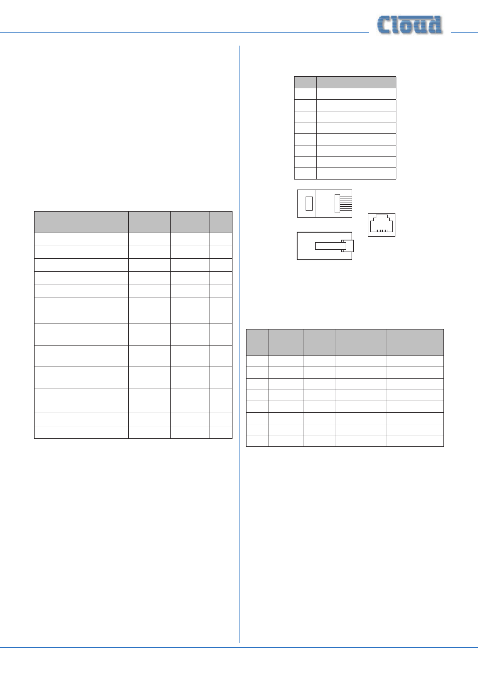
RJ45 pinout
The standard RJ45 wiring convention is as shown below:
PIN
CAT5 CORE
1
White + Orange
2
Orange
3
White + Green
4
Blue
5
White + Blue
6
Green
7
White + Brown
8
Brown
1
8
1
8
1
8
The table below lists the pin allocation of the various
RJ45 sockets on the DCM1’s rear panel (The DCM1e’s
ETHERNET INTERFACE pinout is not included here; this
is wired to the normal Ethernet standard).
PIN
CDPM/
PM
CDR-1
PORTS
EXTENSION
PORTS
MICROPHONE
INPUTS
1
Mic (hot)
Left (cold)
Mic sum (cold)
2
Mic (cold)
Left (hot)
Mic sum (hot)
3
Sense
Sense
4
DC +ve
DC +ve
DC +ve
DC +ve
5
0v
0v
0v
0v
6
DC –ve
DC –ve
7
Data H
Data H
Right (hot)
8
Data L
Data L
Right (cold)