System components, Optional components – Cloud Electronics DCM1 User Manual
Page 7
DCM1 & DCM1e Installation and User Guide v1.0
7
System Components
DCM1/DCM1e
The DCM1 (or DCM1e) is the system “core” and all the
primary audio input sources, zone amplifier inputs, paging
mics/control and all remote controls are connected directly
to it. The DCM1 mainframe should ideally be rack-mounted
along with the audio sources and zone amplifiers, in a central
equipment area.
A practical multi-zone audio system is perfectly realisable with
a DCM1 alone, but system flexibility and ease of operation
will be greatly enhanced by the addition of optional Cloud
remote controls and/or local input modules.
Installing a DCM1e will add the considerable advantage of
external control from a laptop, tablet or other compatible
device using a standard browser application.
Optional components
CDR-1 Series
The CDR-1 Series is a range of remote control plates
specifically designed for use with the DCM1. They are
available in formats suitable for surface mounting (CDR-1)
or flush mounting (CDR-1F), and also in various finishes. They
may be fitted into standard electrical back boxes in whatever
location is convenient in each zone. Any zone may have one
CDR-1, more than one, or none at all. The DCM1 can support
up to 100 CDR-1s. CDR-1s are interconnected with just one
standard Cat 5 UTP cable; units may be daisy-chained at will
and/or connected individually back to the DCM1’s four CDR
ports using almost any wiring topology convenient for the
installation.
The DCM1’s own PSU has the capacity to power up to 8
CDR-1s directly, via the Cat 5 connections. However, please
note that the actual number that can be powered directly
is also dependent on cable length. Full details are provided
with each CDR-1; also see “Cable length and DC power
considerations” on page 21.
The CDR-1 provides the user with local source selection and
level control for the zone in which it is fitted. It additionally
allows selection of any zone groups to which the zone has
been assigned, which gives simple and complete control
over audio in multiple areas which may be split or joined in
different ways at different times.
Once enabled on the DCM1 and a local key code entered,
zone EQ is also adjustable from the CDR-1, allowing audio
optimisation from within the zone itself. An Installer Mode
permits zone assignment and adjustment of other installation
parameters.
CDR-1 variants:
Throughout this manual, all references to “CDR-1” apply
equally to the CDR-1 and the CDR-1F.
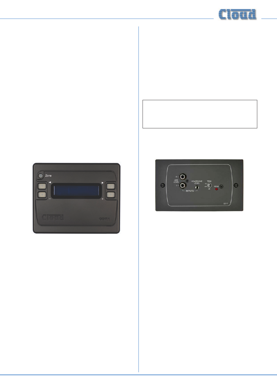
LE-1 Series
LE-1 version illustrated
The LE-1 Series is a range of input connector modules which
can be installed wherever required. Versions are available to
fit standard UK (LE-1) or US (LE-1A) dual-gang electrical
back boxes, or in a “Media” format (LE-1M), which fits a Euro-
style 100 x 50 mm mounting frame.
All versions are available
in either black or white.
They allow connection of a stereo
unbalanced line-level audio source, such as a portable music
player, laptop, radio mic receiver or similar, and connect to
one of the DCM1’s Extension Ports with a single screened
Cat 5 cable.
Multiple LE-1s may be “daisy-chained” together to provide
input points at different locations in the same zone. Signals
applied to modules wired in this way will be summed together.
An internal gating circuit on each module automatically
“disconnects” any chained modules which are not in use, to
minimise noise contribution.
The LE-1’s inputs are electronically buffered to minimise noise
and interference pickup, and input gain is locally adjustable
with a preset control. Two types of input connector are
provided for user convenience: dual phono sockets and a
3.5 mm stereo jack socket; ±12 dB of gain trim adjustment is
available on the faceplate.
Any audio connected to an LE-1 is treated as any other source
and can be routed to any zone in the same manner.