Connections – Cloud Electronics DCM1 User Manual
Page 20
DCM1 & DCM1e Installation and User Guide V1.0
20
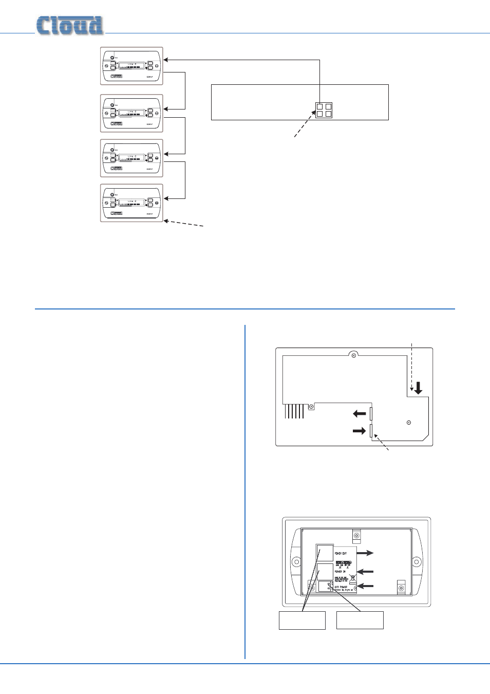
CDR-1 PORTS
PORT
A
PORT
A
PORT
B
PORT
B
Port A termination ON
Termination ON
All other terminations are OFF
DCM1
IN
IN
IN
IN
OUT
OUT
OUT
Network Diagram 3
Note that in the above diagrams there is deliberately no
indication as to which zones any of the CDR-1s are in; this is
because the system imposes no restriction on their physical
location. Interconnection may be made purely on the basis of
wiring convenience.
Connections
CDR-1s are connected to the DCM1’s
CDR-1 PORTS
using standard unscreened Cat 5 cable and RJ45 connectors.
It may be possible to use pre-made Cat 5 “patch cables” to
connect any CDR-1s installed close to the DCM1; otherwise
Cat 5 cable and crimp RJ45 plugs should be used.
NOTE:
All Cat 5 cabling should be wired “pin-to-pin”; “crossed” or
“null” cables will not work.
Wire the RJ45 connectors according to the pinout diagram
on page 69.
Note that the single Cat 5 interconnection provides DC
power as well as data. A full pin allocation of the CDR-1 ports
can be found in the Appendix at the end of this manual.
Any of the four
CDR-1 PORTS may be used. Two of these
are labelled
PORT A and the other two PORT B, but the
four are electrically identical. However, use of Port A or Port
B has relevance to how terminations are set (“Network
Terminations” on page 21).
The CDR-1 and CDR-1F are equipped with two RJ45
connectors, labelled
POWER IN and POWER OUT.
The “first” CDR-1 in a daisy-chain wiring system should be
connected to the DCM1 using its
POWER IN connector.
The
POWER OUT connector on this CDR-1 should be
connected to the
POWER IN of the next CDR-1 in the
chain, and so on until the last CDR-1 in the chain. Note
that the locations of the RJ45 connectors differ on the two
CDR-1 versions:
J2
J1
MI
D
EN
D
ON
OF
F
POWER
OUT
POWER
IN
FROM
DCM-1
EXT POWER
RJ45 SOCKETS FOR
DATA
INTERCONNECTION
CO-AXIAL SOCKET
FOR EXTERNAL PSU
TO NEXT
CDR-1
Data and external power connections on the CDR-1
RJ45 SOCKETS FOR
DATA
INTERCONNECTION
2-PIN EXTERNAL
POWER SOCKET
TO NEXT CDR
FROM DCM-1
Data and external power connections on the CDR-1F