Hypertherm HSD130 HySpeed Plasma User Manual
Page 185
MAINTENANCE
HySpeed HSD130 RHF
Instruction Manual
5-39
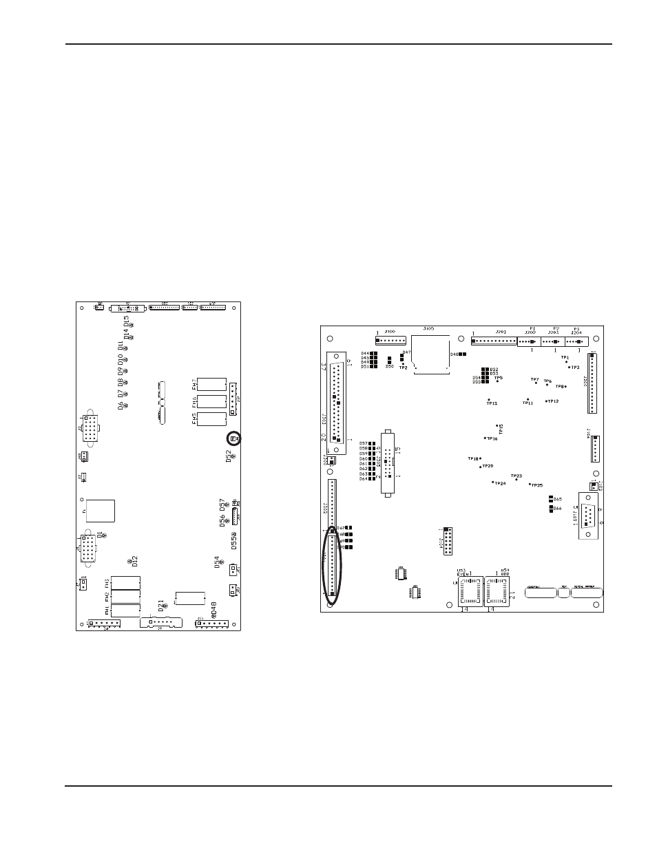
4. Remove J3.8 from PCB3 and place a jumper wire between pins 1 and 2 on the cable connector.
a. Make a test cut. If the phase-loss error continues, verify wiring between the connectors J3.8 on PCB3 and
J4.301 on the power supply control board (PCB4) by verifying the continuity between
– J3.8 pin1 to J4.301 pin13
– J3.8 pin2 to J4.301 pin14.
b. If the wiring is OK, replace PCB4. If any wiring is damaged, repair or replace damaged wires.
c. If the phase-loss error goes away while the jumper is on J3.8, make another cut and measure the phase-to-
phase voltage across the fuses F5, F6, and F7. The voltage should be 220 VAC +/–15%. If one of the
3 voltage readings is less than 187 VAC, check the contacts to the contactor, and check for loose connections
between the power cord, contactor, power transformer, and the chopper.
041938
0
4
1935
Power distribution board (PCB3)
Power supply control board (PCB4)