Installation requirements – standard system -4, Grounding diagram -12 – Hypertherm HSD130 HySpeed Plasma User Manual
Page 80
Advertising
INSTALLATION
3-12
HySpeed HSD130 RHF
Instruction Manual
**
**
**
A
C
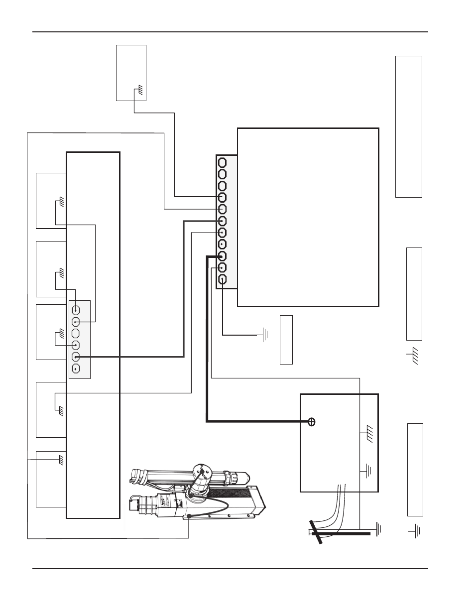
earth/service ground
Ground rod
Chassis and R
F
I ground
T
he lifter assembly and the R
H
F console eac
h
require a separate path to the cutting t
able
ground bus bar
.
Cutting t
able
Plasma
power supply
P
ositive D
C
Command
TH
C
Bus bar
Bus bar
Command
TH
C
RHF
console
Metering
console
Gas/Selection
console
CNC
console
Grounding diagram
(some systems will not include all the components shown)
Gantry
Advertising
See also other documents in the category Hypertherm Equipment:
- EDGE Pro Ti Shape Cutting Control Rev.2 (288 pages)
- 80669J Rev.3 (304 pages)
- HD3070 Plasma Arc Cutting System w/ Manual Gas Console (281 pages)
- MAXPRO200 Rev.2 (294 pages)
- MicroEDGE Pro Shape Cutting Control Rev.2 (182 pages)
- Powermax1650 (317 pages)
- HPR260 Auto Gas Preventive Maintenance Program Rev.4 (288 pages)
- Shape Cutting Control (66 pages)
- PHC Sensor (58 pages)
- HTA Rev 6.00 Operators Manual (212 pages)
- HTA Rev 7.00 Install Guide (242 pages)
- THC Control Board Replacement (13 pages)
- THC Plasma Interfacer Upgrade (9 pages)
- THC X-Y Table Product Configuration (20 pages)
- D845GERG2 (128 pages)
- MRT2 (64 pages)
- MRT (98 pages)
- Duramax Hyamp Long Handheld Torches (92 pages)
- Duramax Hyamp Robotic Torch (74 pages)
- HyIntensity Fiber Laser Rev.3 (240 pages)
- PCBS-0124 (70 pages)
- SuperMicro 370SBA 533Mhz (90 pages)
- LR2075 (56 pages)
- Phoenix 8.0 (585 pages)
- LH2125 (60 pages)
- HD3070 w/ Automatic Gas (35 pages)
- HD3070 w/Manual Gas (43 pages)
- HD4070 Rev.8 (278 pages)
- HD4070 Product Configuration (88 pages)
- HPR800XD Manual Gas Preventive Maintenance Program Rev.1 (32 pages)
- HPR800XD Manual Gas Preventive Maintenance Program Rev.1 (33 pages)
- HPR800XD Manual Gas Rev.2 (368 pages)
- HPRXD Short Torch with Integrated Lead Rev.1 (30 pages)
- HT4001 (59 pages)
- DuraChill 5 HP Air-Cooled Chiller For Hypertherm (29 pages)
- HT4001 Air Injected Water Muffler System (40 pages)
- H601 Power Supplies (62 pages)
- MAX200 Remote Switch (9 pages)
- HT4100 Plasma Arc Cutting System Operating (50 pages)
- HT4001 Plasma Arc Cutting System (259 pages)
- HySpeed HT2000 Plasma Arc Cutting System Rev.7 (53 pages)
- HySpeed HT2000 Plasma Arc Cutting System Rev.27 (289 pages)
- MAX200 Water Muffler (39 pages)
- HT2000LHF Product Configuration (23 pages)