HEIDENHAIN TNC 640 (34059x-05) User Manual
Page 270
Programming: Data Transfer from CAD Files
7.3
DXF converter (Option #42)
7
270
TNC 640 | User's Manual
HEIDENHAIN Conversational Programming | 1/2015
The TNC also transfers two workpiece-blank
definitions (
BLK FORM) to the contour program. The
first definition contains the dimensions of the entire
DFX file. The second one, which is the active one,
contains only the selected contour elements, so that
an optimized size of the workpiece blank results.
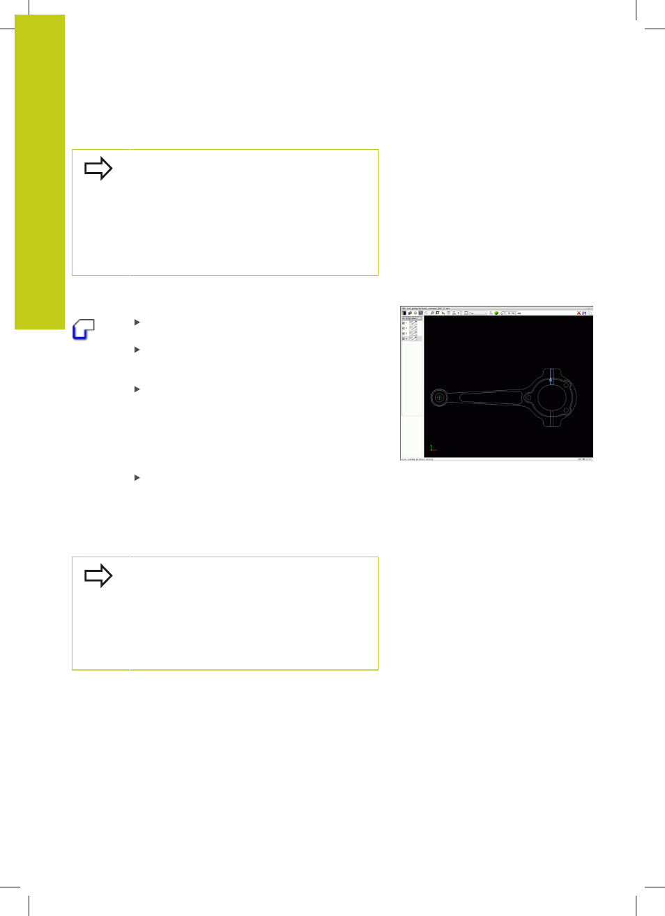
The TNC only saves elements that have actually been
selected (blue elements), which means that they
have been given a check mark in the left window.
Dividing, extending and shortening contour elements
Proceed as follows to modify contour elements:
The graphics window is active for the contour
selection
To select the starting point: Select an element or
the intersection between two elements (with the
shift key). A red star is shown as the starting point
To select the next contour element: Click the
desired element with the mouse. The TNC
displays the machining sequence as a dashed
straight line. When the element is selected the
TNC displays it in blue. If the elements cannot be
connected, the TNC displays the selected element
in gray
If further contour elements in the selected
machining sequence are selectable, these
elements turn green. With divergences, the
element with the lowest angle distance is
selected. Click on the last green element to
assume all elements into the contour program
You select the machining sequence of the contour
with the first contour element.
If the contour element to be extended or shortened
is a straight line, then the TNC extends/shortens the
contour element along the same line. If the contour
element to be extended or shortened is a circular arc,
then the TNC extends/shortens the contour element
along the same arc.