Graphical display of turning operations – HEIDENHAIN TNC 640 (34059x-05) User Manual
Page 491
Basic functions (Option 50) 14.2
14
TNC 640 | User's Manual
HEIDENHAIN Conversational Programming | 1/2015
491
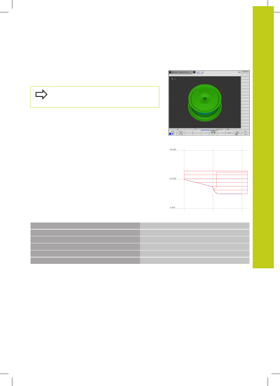
Graphical display of turning operations
You can simulate turning operations in the
Test Run mode. The
requirement for this is a workpiece blank definition suitable for the
turning process and Option #20.
The machining times shown for milling/turning
operations in the simulation do not correspond to the
actual machining times.
Graphic display in the Programming mode of operation
You can graphically simulate turning processes with the line
graphic in
Programming operating mode. To display the traverse
movements in turning mode in the
Programming operating mode,
change the layout using the soft keys, see "Generating a graphic for
an existing program", page 153.
The standard assignment of the axes with turning is defined so that
the X coordinates describe the diameter of the workpiece and the Z
coordinates the longitudinal positions.
Even when turning occurs in a 2D plane (X and Z coordinates), with
a rectangular workpiece blank you must still program the Y values
when defining the workpiece blank.
NC syntax
0 BEGIN PGM SHOULDER MM
1 BLK FORM 0.1Y X+0 Y-1 Z-50
Workpiece blank definition
2 BLK FORM 0.2 X+87 Y+1 Z+2
3 TOOL CALL 12
Tool call
4 M140 MB MAX
Retract the tool
5 FUNCTION MODE TURN
Activate Turning mode