Yaskawa CIMR-PUxA User Manual
Page 107
No.
Parameter Name
Setting Range
Default
E2-01
Motor Rated Current
10% to 200% of the drive
rated current
<1>
Determined by
o2-04
<1> Display is in the following units:
2A0004 to 2A0040, 4A0002 to 4A0023, and 5A0007 to 5A0017: 0.01 A units.
2A0056 to 2A0415, 4A0031 to 4A0675, and 5A0022 to 5A0242: 0.1 A units.
4A0930 and 4A1200: 1 A units.
Note:
An oPE02 error will occur if the motor rated current in E2-01 is set lower than the motor no-load current in E2-03. Set E2-03 correctly to
prevent this error.
n
H1-01 to H1-08: Functions for Terminals S1 to S8
.
No.
Parameter Name
Setting
Range
Default
H1-01
Multi-Function Digital Input Terminal S1 Function Selection
1 to 9F
40 (F)
<1>
: Forward Run Command (2-Wire sequence)
H1-02
Multi-Function Digital Input Terminal S2 Function Selection
1 to 9F
41 (F)
<1>
: Reverse Run Command (2-Wire sequence)
H1-03
Multi-Function Digital Input Terminal S3 Function Selection
0 to 9F
24: External Fault
H1-04
Multi-Function Digital Input Terminal S4 Function Selection
0 to 9F
14: Fault Reset
H1-05
Multi-Function Digital Input Terminal S5 Function Selection
0 to 9F
3 (0)
<1>
: Multi-Step Speed Reference 1
H1-06
Multi-Function Digital Input Terminal S6 Function Selection
0 to 9F
4 (3)
<1>
: Multi-Step Speed Reference 2
H1-07
Multi-Function Digital Input Terminal S7 Function Selection
0 to 9F
6 (4)
<1>
: Jog Reference Selection
H1-08
Multi-Function Digital Input Terminal S8 Function Selection
0 to 9F
8: (6)
<1>
: External Baseblock Command
<1> Number appearing in parenthesis is the default value after performing a 3-Wire initialization (A1-03 = 3330).
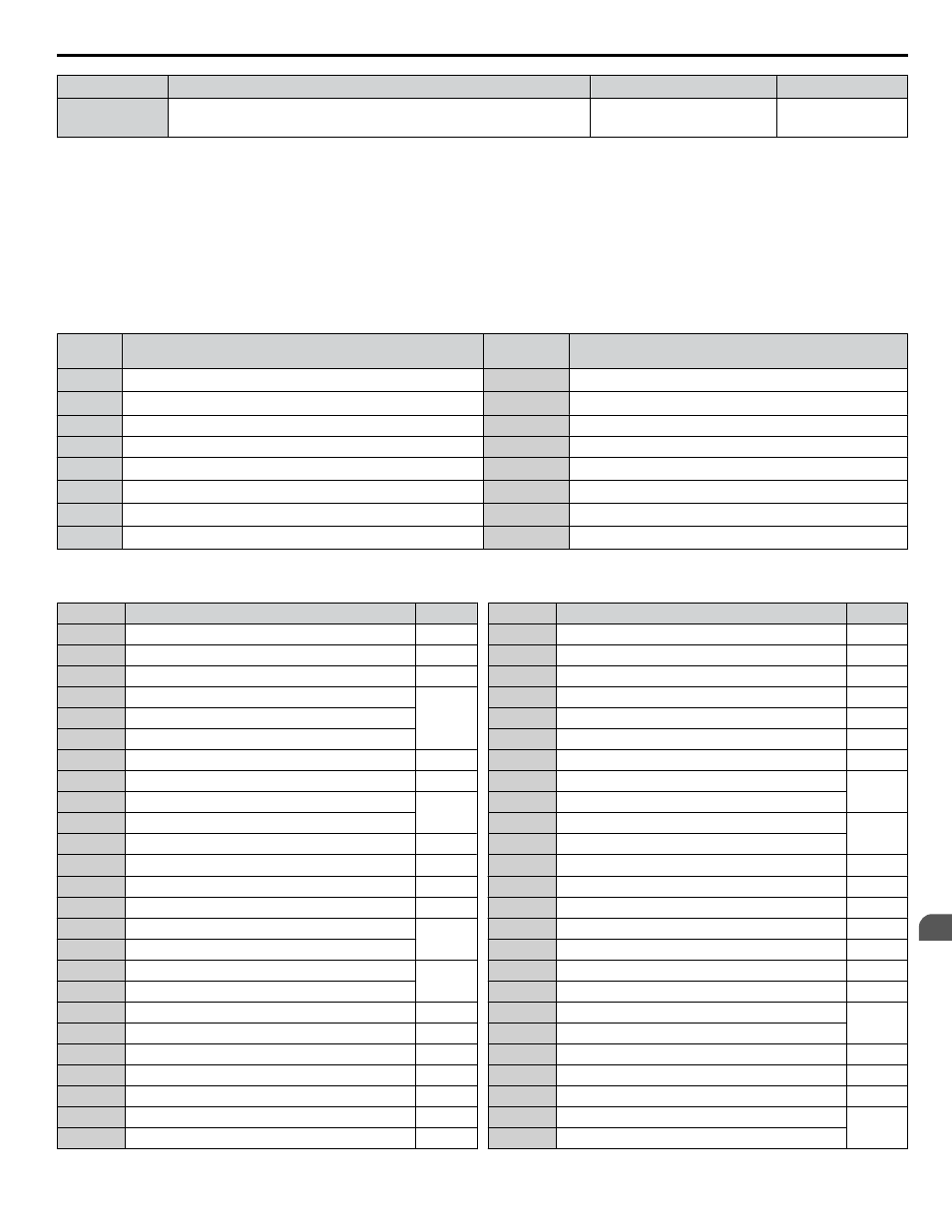
Table 4.27 Multi-Function Digital Input Terminal Settings
Setting
Function
Page
0
3-Wire Sequence
1
LOCAL/REMOTE Selection
—
2
External Reference 1/2 Selection
—
3
Multi-Step Speed Reference 1
—
4
Multi-Step Speed Reference 2
5
Multi-Step Speed Reference 3
6
Jog reference Selection
—
7
Accel/Decel Time Selection 1
—
8
Baseblock Command (N.O.)
—
9
Baseblock Command (N.C.)
A
Accel/Decel Ramp Hold
—
B
Drive Overheat Alarm (oH2)
—
C
Analog Terminal Input Selection
—
F
Through Mode
—
10
Up Command
—
11
Down Command
12
Forward Jog
—
13
Reverse Jog
14
Fault Reset
—
15
Fast Stop (N.O.)
—
17
Fast Stop (N.C.)
—
18
Timer Function Input
—
19
PID Disable
—
1A
Accel/Decel Time Selection 2
—
1B
Program Lockout
—
Setting
Function
Page
1E
Reference Sample Hold
—
20 to 2F External Fault
—
30
PID Integral Reset
—
31
PID Integral Hold
—
32
Multi-Step Speed Reference 4
—
34
PID Soft Starter Cancel
—
35
PID Input Level Selection
—
40
Forward Run Command (2-Wire sequence)
—
41
Reverse Run Command (2-Wire sequence)
42
Run Command (2-Wire sequence 2)
—
43
FWD/REV Command (2-Wire sequence 2)
47
Node Setup
—
51
Disable Sequence Timers
—
52
Cancel Active Sequence Timer
—
60
DC Injection Braking Command
—
61
External Speed Search Command 1
—
62
External Speed Search Command 2
—
63
Field Weakening
—
65
KEB Ride-Thru 1 (N.C.)
—
66
KEB Ride-Thru 1 (N.O.)
67
Communications Test Mode
—
68
High Slip Braking (HSB)
—
6A
Drive Enabled
—
75
Up 2 Command
—
76
Down 2 Command
4.6 Basic Drive Setup Adjustments
YASKAWA ELECTRIC TOEP YAIP1U 01B YASKAWA AC Drive - P1000 Quick Start Guide
107
4
Start-Up Programming & Operation