L4: speed detection – Yaskawa CIMR-PUxA User Manual
Page 213
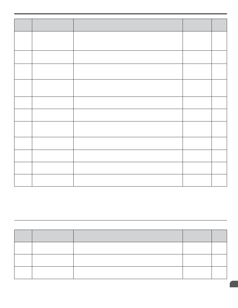
No.
(Addr.
Hex)
Name
Description
Values
Page
L3-05
(493)
Stall Prevention Selection
during Run
0: Disabled. Drive runs at a set frequency. A heavy load may cause speed loss.
1: Decel time 1. Uses the deceleration time set to C1-02 while Stall Prevention
is performed.
2: Decel time 2. Uses the deceleration time set to C1-04 while Stall Prevention
is performed.
Default: 1
Range: 0 to 2
L3-06
(494)
Stall Prevention Level
during Run
Enabled when L3-05 is set to 1 or 2. 100% is equal to the drive rated current. Default:
<1>
Min.: 30%
Max.: 150%
<1>
L3-11
(4C7)
Overvoltage Suppression
Function Selection
Enables or disables the ov suppression function, which allows the drive to
change the output frequency as the load changes to prevent an ov fault.
0: Disabled
1: Enabled
Default: 0
Range: 0, 1
–
L3-17
(462)
Target DC Bus Voltage for
Overvoltage Suppression
and Stall Prevention
Sets the desired value for the DC bus voltage during overvoltage suppression
and Stall Prevention during deceleration.
Default: 375 Vdc
<2> <3>
Min.: 150
Max.: 400
<3>
–
L3-20
(465)
DC Bus Voltage Adjustment
Gain
Sets the proportional gain for KEB Ride-Thru, Stall Prevention, and
overvoltage suppression.
Default: 1.00
Min.: 0.00
Max.: 5.00
–
L3-21
(466)
Accel/Decel Rate
Calculation Gain
Sets the proportional gain used to calculate the deceleration rate during KEB
Ride-Thru, ov suppression function, and Stall Prevention during deceleration
(L3-04 = 2).
Default: 1.00
Min.: 0.10
Max.: 10.00
–
L3-23
(4FD)
Automatic Reduction
Selection for Stall
Prevention during Run
0: Sets the Stall Prevention level set in L3-04 that is used throughout the entire
frequency range.
1: Automatic Stall Prevention level reduction in the constant output range. The
lower limit value is 40% of L3-06.
Default: 0
Range: 0, 1
–
L3-24
(46E)
Motor Acceleration Time for
Inertia Calculations
Sets the time needed to accelerate the uncoupled motor at rated torque from
stop to the maximum frequency.
Default:
<4> <5>
Min: 0.001 s
Max: 10.000 s
–
L3-25
(46F)
Load Inertia Ratio
Sets the ratio between the motor and machine inertia.
Default: 1.0
Min.: 1.0
Max.: 1000.0
–
L3-26
(455)
Additional DC Bus
Capacitors
When DC bus capacitors have been added externally, be sure to add those
values to the internal capacitor table for proper DC bus calculations.
Default: 0 μF
Min: 0
Max: 65000
–
L3-27
(456)
Stall Prevention Detection
Time
Sets the time the current must exceed the Stall Prevention level to activate
Stall Prevention.
Default: 50 ms
Min.: 0
Max.: 5000
–
<1> Upper limit is dependent on parameter L8-38, Frequency Reduction Selection.
<2> Default setting is dependent on parameter E1-01, Input voltage Setting.
<3> Values shown are specific to 200 V class drives. Double the value for 400 V class drives. Multiply the value by 2.875 for 600 V class drives, but
set the value below 1040 Vdc (overvoltage protection level).
<4> Parameter value changes automatically if E2-11 is manually changed or changed by Auto-Tuning.
<5> Default setting is dependent on parameter o2-04, Drive Model Selection.
u
L4: Speed Detection
No.
(Addr.
Hex)
Name
Description
Values
Page
L4-01
(499)
Speed Agreement Detection
Level
L4-01 sets the frequency detection level for digital output functions
H2-oo = 2, 3, 4, 5.
Default: 0.0 Hz
Min.: 0.0
Max.: 400.0
–
L4-02
(49A)
Speed Agreement Detection
Width
L4-02 sets the hysteresis or allowable margin for speed detection.
Default: 2.0
Min.: 0.0
Max.: 20.0
–
L4-03
(49B)
Speed Agreement Detection
Level (+/-)
L4-03 sets the frequency detection level for digital output functions
H2-oo = 13, 14, 15, 16.
Default: 0.0 Hz
Min.: -400.0
Max.: 400.0
–
B.7 L: Protection Function
YASKAWA ELECTRIC TOEP YAIP1U 01B YASKAWA AC Drive - P1000 Quick Start Guide
213
B
Parameter List