Yaskawa CIMR-PUxA User Manual
Page 148
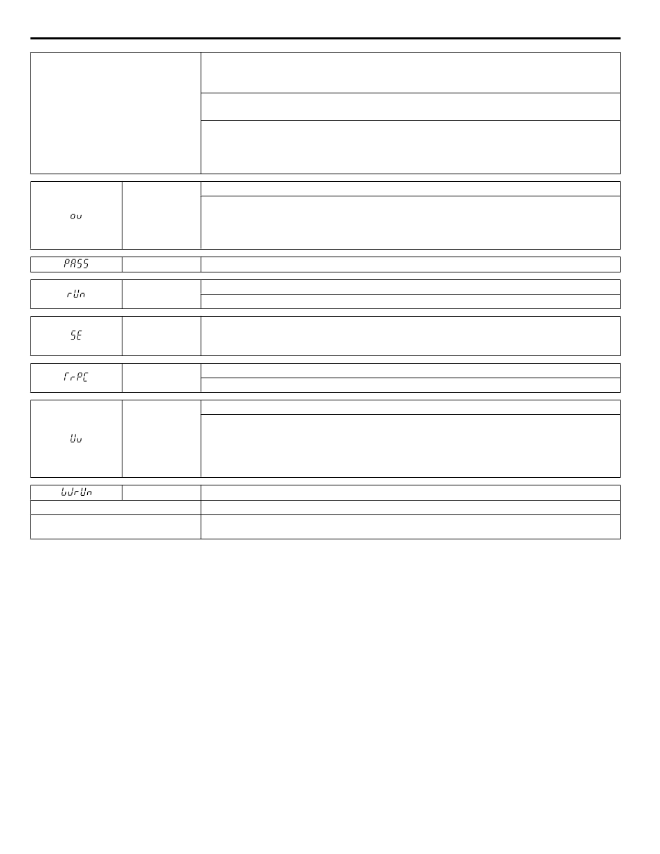
Motor has overheated
• Check the size of the load, the accel/decel times, and the cycle times.
• Decrease the load.
• Increase the acceleration and deceleration times (C1-01 through C1-04).
• Adjust the preset V/f pattern (E1-04 through E1-10) by reducing E1-08 and E1-10.
• Do not set E1-08 and E1-10 too low. This reduces load tolerance at low speeds.
• Check the motor rated current.
• Enter the motor rated current to parameter E2-01 as indicated on the motor nameplate.
• Ensure the motor cooling system is operating normally.
• Repair or replace the motor cooling system.
ov
DC Bus Overvoltage
The DC bus voltage exceeded the trip point.
• For 200 V class drives: approximately 410 V
• For 400 V class drives: approximately 820 V (740 V when E1-01 is less than 400)
• For 600 V class drives: approximately 1040 V
PASS
MEMOBUS/Modbus Comm. Test Mode Complete
rUn
Motor Switch during Run
A command to switch motors was entered during run.
SE
MEMOBUS/Modbus Communication Test Mode Error
Note:
This alarm will not trigger a multi-function output terminal that is set for alarm output
(H2-oo = 10).
TrPC
IGBT Maintenance Time (90%)
IGBTs have reached 90% of their expected performance life.
Uv
Undervoltage
One of the following conditions was true when the drive was stopped and a Run command was entered:
• DC bus voltage dropped below the level specified in L2-05.
• Contactor to suppress inrush current in the drive was opened.
• Low voltage in the control drive input power. This alarm outputs only if L2-01 is not 0 and DC bus voltage
is under L2-05.
WrUn
Waiting for Run
Cause
Possible Solutions
The Run command has been applied and
the b1-11 timer is active.
Adjust b1-11 to the desired delay time. The drive sill start normally after the b1-11 timer expires.
5.3 Alarm Detection
148
YASKAWA ELECTRIC TOEP YAIP1U 01B YASKAWA AC Drive - P1000 Quick Start Guide