Single drive installation, 1 mechanical installation – Yaskawa CIMR-PUxA User Manual
Page 27
n
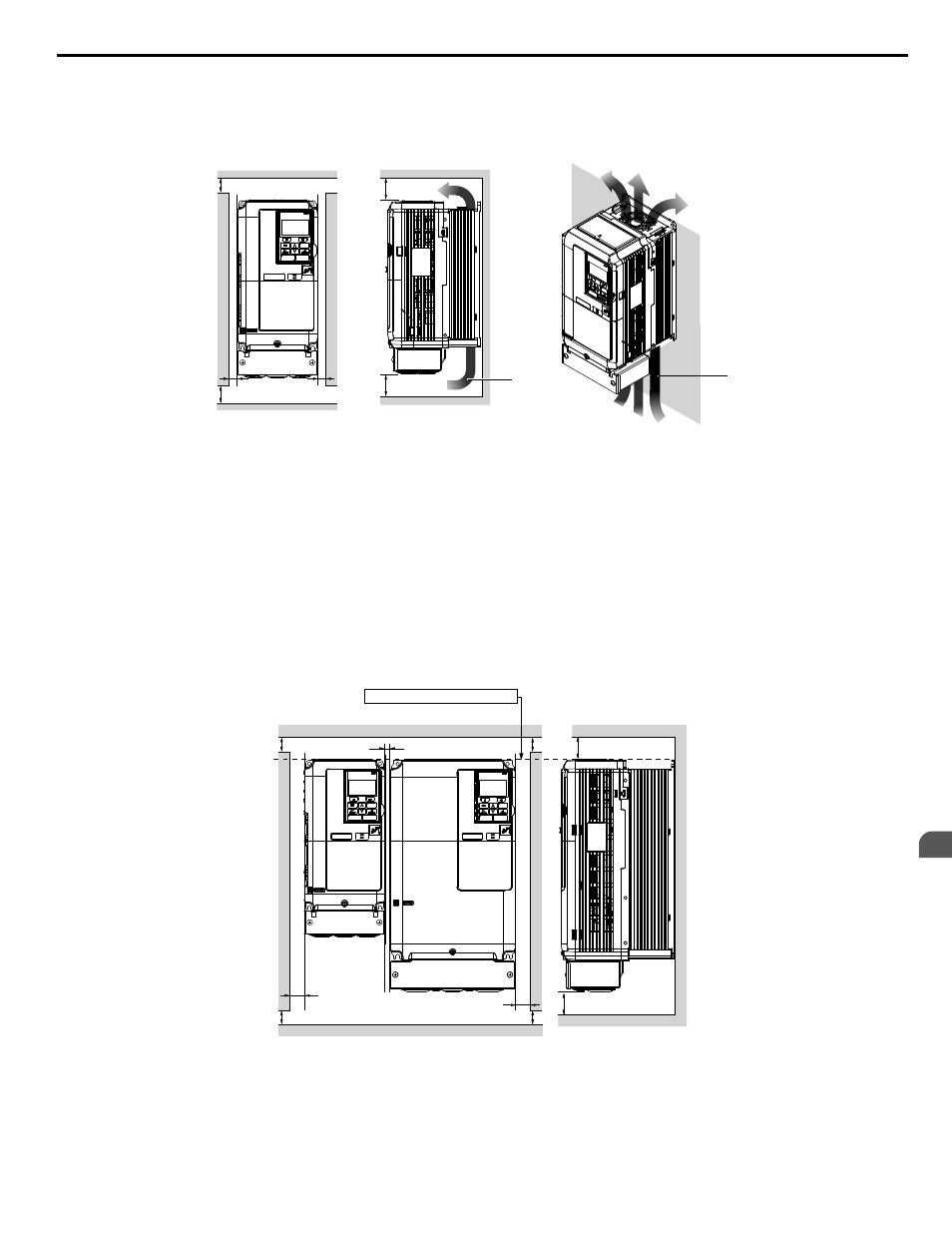
Single Drive Installation
against a closed surface to avoid diverting cooling air around the heatsink.
A
A
B
B
Side Clearance
Top/Bottom Clearance
C
C
D
D
A – 50 mm minimum
B – 30 mm minimum
C – 120 mm minimum
D – Airflow direction
Figure 2.2 Correct Installation Spacing
Note:
IP20/NEMA Type 1 enclosure and IP00/Open Type enclosure models require the same amount of space above and below the drive for
installation.
n
Multiple Drive Installation (Side-by-Side Installation)
Models 2A0004 to 2A0081, 4A0002 to 4A0044, and 5A0003 to 5A0032 can take advantage of Side-by-Side installation.
When installing multiple drives into the same enclosure panel, mount the drives according to
and set L8-35,
Installation Method Selection, to 1 (Side-by-Side Mounting).
When mounting drives with the minimum clearance of 2 mm according to
, set parameter L8-35 to 1 while
Refer to Parameter List on page 183
A
A
A
A
B
C
B
Side Clearance
Line up the tops of the drives.
D
D
Top/Bottom Clearance
A – 50 mm minimum
B – 30 mm minimum
C – 2 mm minimum
D – 120 mm minimum
Figure 2.3 Space Between Drives (Side-by-Side Mounting)
Note:
Align the tops of the drives when installing drives of different heights in the same enclosure panel. Leave space between the tops and bottoms
of stacked drives for easier cooling fan replacement.
2.1 Mechanical Installation
YASKAWA ELECTRIC TOEP YAIP1U 01B YASKAWA AC Drive - P1000 Quick Start Guide
27
2
Mechanical Installation