Test run checklist, 10 test run checklist – Yaskawa CIMR-PUxA User Manual
Page 124
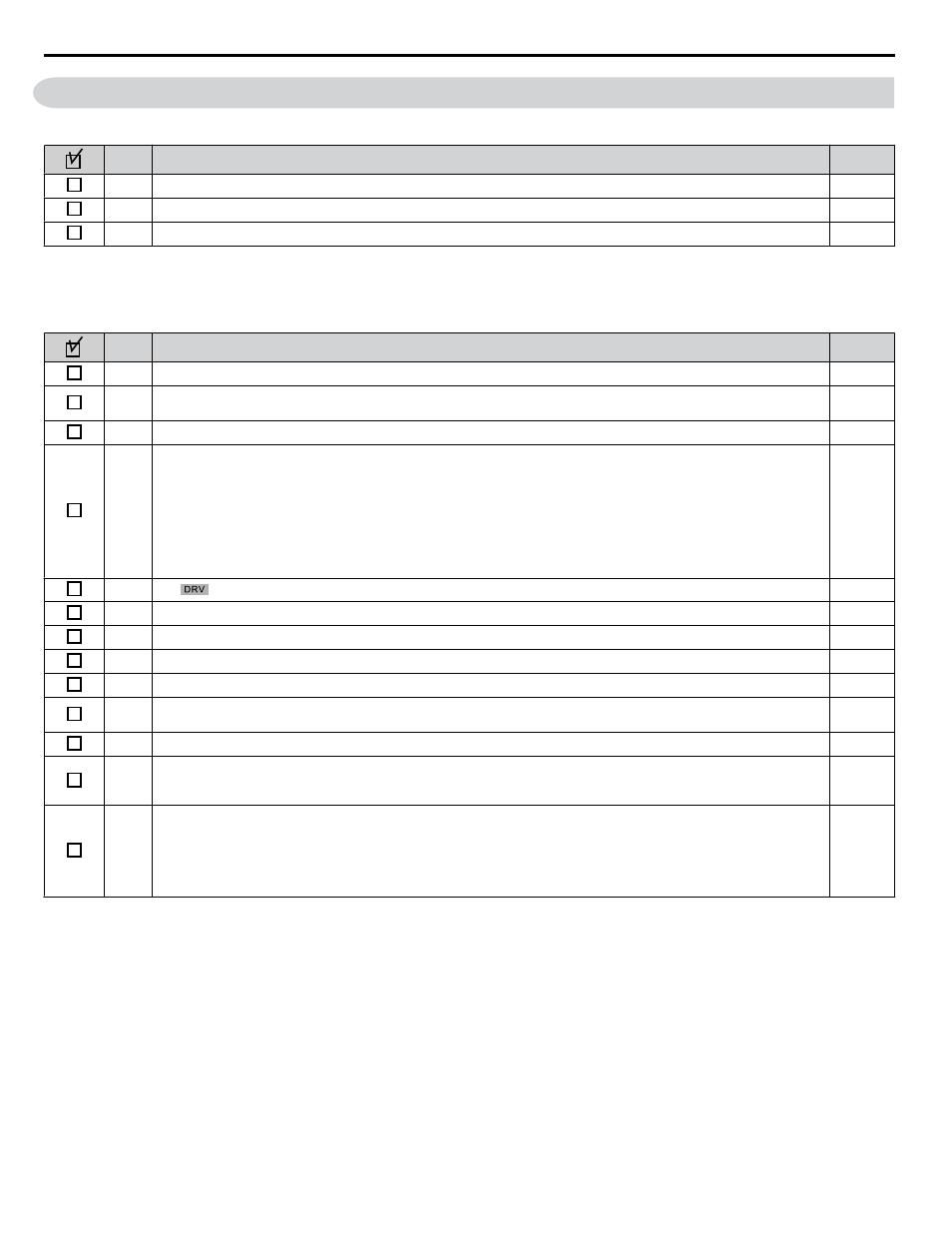
4.10 Test Run Checklist
Review the checklist before performing a test run. Check each item that applies.
No.
Checklist
Page
1
Thoroughly read the manual before performing a test run.
–
2
Turn the power on.
3
Set the voltage for the power supply to E1-01.
Check the items that correspond to the control mode being used.
WARNING!
Sudden Movement Hazard. Ensure start/stop and safety circuits are wired properly and in the correct state before energizing
the drive. Failure to comply could result in death or serious injury from moving equipment. When programmed for 3-Wire control, a momentary
closure on terminal S1 may cause the drive to start.
No.
Checklist
Page
4
Select the best V/f pattern according to the application and motor characteristics.
–
5
Select Stationary Auto-Tuning for Line-to-Line Resistance or Rotational Auto-Tuning for V/f Control if using Energy
Saving functions.
6
Decouple the motor for Rotational Auto-Tuning for V/f Control.
7
Enter the following data depending on Auto-Tuning method according to the information listed on the motor nameplate:
• Motor rated power to T1-02 (kW)
• Motor rated voltage to T1-03 (V)
• Motor rated current to T1-04 (A)
• Motor base frequency to T1-05 (Hz)
• Number of motor poles to T1-06
• Motor base speed to T1-07 (r/min)
–
8
The
should light after giving a Run command.
–
9
To give Run command and frequency reference from the digital operator, press “LO/RE” key to set to LOCAL.
10
If the motor rotates in the opposite direction during test run, switch two of U/T1, V/T2, W/T3, or change b1-14.
11
Set motor rated current (E2-01) and motor protection (L1-01) values for motor thermal protection.
–
12
Set the drive for REMOTE when control circuit terminals provide the Run command and frequency reference.
13
If the control circuit terminals should supply the frequency reference, select the correct voltage input signal level
(0 to +10 V or -10 to +10 V) or the correct current input signal level (4 to 20 mA or 0 to 20 mA).
14
Set the proper signal level to terminals A1, A2, A3 (0 to 20 mA, 4to 20 mA, 0 to +10 V or -10 to +10 V).
15
For A1, A2, and A3, when current input is used, switch the jumper on S1 from the V-side to I-side. Set the level for current
signal used with parameter H3-01 for terminal A1, H3-09 for terminal A2, H3-05 for terminal A3, (set “2” for 4 to 20
mA, or “3” for 0 to 20 mA). V = Voltage, I = Current analog input signal.
16
If an analog input supplies the frequency reference, make sure it produces the desired frequency reference. Make the
following adjustments if the drive does not operate as expected:
Gain adjustment: Set the maximum voltage/current signal and adjust the analog input gain (H3-03 for A1, H3-11 for A2,
H3-07 for A3) until the frequency reference value reaches the desired value.
Bias adjustment: Set the minimum voltage/current signal and adjust the analog input bias (H3-04 for A1, H3-12 for A2,
H3-08 for A3) until the frequency reference value reaches the desired minimum value.
–
4.10 Test Run Checklist
124
YASKAWA ELECTRIC TOEP YAIP1U 01B YASKAWA AC Drive - P1000 Quick Start Guide