2 alarm input port, Alarm input port – AGI Security SYS-16HN44P User Manual
Page 87
75
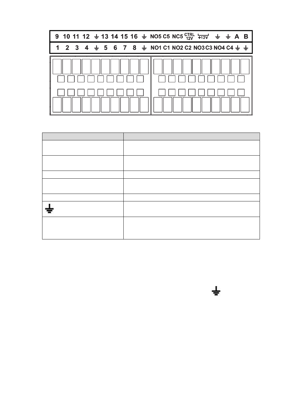
Figure 2-44
Icon
Function
1~16
ALARM1~ALARM16. The alarm becomes activated in the
low level.
NO1 C1,NO2 C2,NO3 C3,NO4
C4
Four NO activation output groups. (On-off button).
NO5 C5 NC5
One NO/NC activation output group. (On-off button).
CTRL 12V
Control power output. Disable power output when alarm is
canceled. Current is 500mA.
+12V
Rated current output. Current is 500mA.
GND
A/B
485 communication port. They are used to control devices
such as PTZ. Please parallel connect 120T
Ω between A/B
cables if there are too many PTZ decoders.
Note
Different models support different alarm input ports. Please refer to the specifications sheet for
detailed information.
Slight difference may be found on the alarm port layout.
2.3.2 Alarm input port
Connect the positive end (+) of the alarm input device to the alarm input port (ALARM IN 1~16) of the
NVR. Connect the negative end (-) of the alarm input device to the ground end (
) of the NVR.