Zone sensor, Expansion boards, Tl ha an i d – Auto-Zone Control Systems Auto-Zone Plus Systems Installation & Operation (Version 03A) User Manual
Page 13: Ph ili ps
Auto-Zone Plus
Section
1
Design Guide 1-9
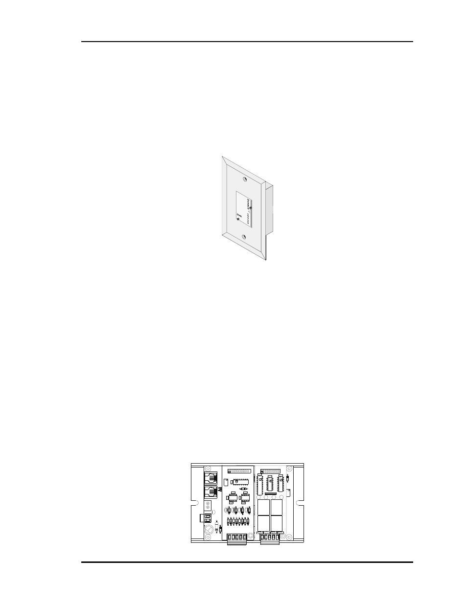
Zone Sensor
The patented zone sensor is of a flush, wall mounted design. A special plate on the face
of the sensor accurately senses space conditions. As a result of its unique design, the zone
sensor rejects the influence of internal wall temperature effects. The sensor comes in four
different configurations:
• Sensor only
• Sensor w/push-button override (Override time fixed at 2 hours)
• Sensor w/setpoint adjustment
• Sensor w/override & setpoint adjustment
Any combination of these sensor configurations can be used with the system.
Expansion Boards
The Zone Manager is designed to utilize expansion boards to provide additional
versatility to the control system. The OE352 2 Slot Expansion Base Board connects to the
Zone Manager via a modular cable and with the OE355 4 Analog Output Expansion
Board mounted on it can provide for 2 additional analog outputs to control a modulating
hot water heating valve or SCR electric heater and/or modulating chilled water valve. The
OE357 4 Relay Output Board can also be mounted on the 2 Slot Expansion Base Board
and provides for up to 6 total stages of heating and/or cooling combined when two
OE357 Boards are used.
VR5
M
C
7
8
2
4
C
T
C6
TB2
VR3
7
8
0
5
A
C
T
R1
4
VR2
D
3
7
8
2
4
C
T
M
C
M
C
VR4
7
8
1
2
C
T
M
C
GND
+24VDC-OUT
GND
24VAC-IN
TB1
P82B715P
CX3
R13
PWR
LD1
C1
PJ2
R11
C2
C3
U1
PJ1
R9
R7
D2
D1
R8
P1
R1
CX1
R2 R3
JP1
2 S
LO
T M
O
D
UL
AR
I/O
VR6
7
8
2
4
C
T
M
C
LM
35
8N
YS
10
17
80
C4
C5
U2
VR1
R12
R6
CX2
R10
R4 R5
P2
JP2
GN
D
AO
U
T
1
Y
S
1017
86
4
A
OUT
M
OD.
I/
O
B
D
.
CX
1
U1
Q1
LM358
R2
U2
R9
D1
R6
D2
R7
D4
D3
R8
TB1
CX
2
C3
C1
P1
RV1
R1
C4
U3
C2
LM358
CX
3
AO
U
T
2
AO
U
T
3
AO
U
T
4
Q2
R3
Q4
Q3
R4
R5
UL
5
A2
50
VA
C
G
5L-
11
4P
-P
S
O
M
RO
N
C
O
N
TA
C
T:
24
VD
C
UL
5
A2
50
VA
C
G
5L-
11
4P
-P
S
O
M
RO
N
C
O
N
TA
C
T:
24
VD
C
UL
5
A2
50
VA
C
G
5L-
11
4P
-P
S
O
M
RO
N
C
O
N
TA
C
T:
24
VD
C
UL
5
A2
50
VA
C
G
5L-
11
4P
-P
S
O
M
RO
N
C
O
N
TA
C
T:
24
VD
C
K3
K2
4R
LY
I
O
B
D
.
V4
K4
YS
10
17
90
TB1
V1
K1
K3
U2
K4
RN
1
PC
F8
57
4P
U3
C
X3
U1
T
L
HA AN I D
UL
N
28
03
A/
K2
K1
74
H
C
04
N
PH
ILI
PS
P1
CX2
CX1