4 zone manager bypass damper wiring checks, Figure 4-11: bypass actuator troubleshooting – Auto-Zone Control Systems Auto-Zone Plus Systems Installation & Operation (Version 03A) User Manual
Page 186
Section 4
Auto-Zone Plus
4-36
Start-Up and Troubleshooting
2.3.4
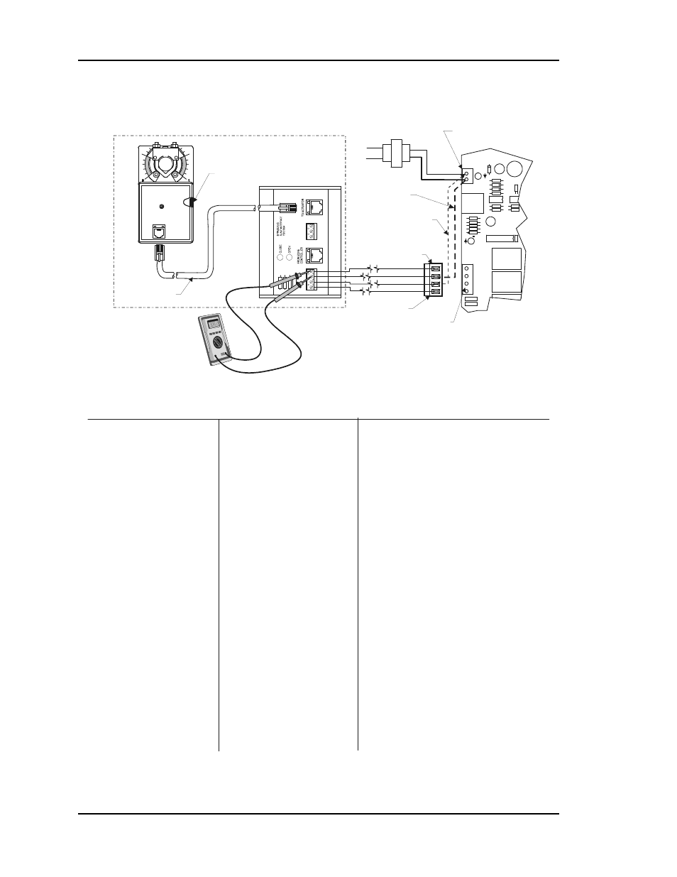
Zone Manager Bypass Damper Wiring Checks
Meter Should Measure Approximately
5000 Ohms With Actuator In Middle
Of Full Travel Position. See Item #3 Below
For Instructions.
+
-
Bypass
Actuator
OE512, OE741 & OE282-02 Bypass Damper Package
Zone Manager Board
Transformer
PWR
V4
V3
CLOSE
OPEN
FDBK
GND
GND
24VAC
NE5090
Line
Voltage
GND
24VAC
Actuator Clutch
Modular Cable
Bypass Damper Components & Wiring
Power Connection Terminal
Jumper Wire Between
24VAC And Open Or Close
Terminal As Required
Jumper Wire
Between 24VAC
And Ground
Remove Terminal Plug
From Zone Manager Board
When Performing Jumper
Testing Of Actuator
Bypass Damper
Terminal Plug
Bypass Damper
Terminal Socket
FDBK
OPEN
GND
GND
PJ1
PJ2
LD
2
LD
1
OPEN
CLOSE
CLOSE
TB1
TB2
(PL101824) BYPASS AND
SLAVE INTERFACE CARD
1.) Confirm That All Wiring Is Correctly
Connected To The Bypass & Slave
Interface Card Terminals And The Zone
Manager Bypass Actuator Terminals. Be
Sure The Modular Cable Is Plugged In To
Both The Actuator And The Modular Plug
Labeled "To Actuator" On The Bypass &
Slave Interface Card. If No Wiring Errors
Are Found, Proceed To The Next Step.
2.) Remove Communications Wiring From
The Zone Manager Board Then Remove
The Power From The Zone Manager
Board. Go To The Bypass Damper
Location And Depress Clutch On The
Actuator. Rotate The Actuator Clamp And
Damper Shaft Back And Forth. Check To
Verify That The Damper Moves Freely
From Full Open To Full Closed Position.
Check For Binding Or Interference That
Prevents Full Opening And Closing Of The
Bypass Damper. If The Damper Appears
To Move Freely Proceed To The Next Step.
3.) Depress The Clutch On The Actuator.
Rotate The Damper Shaft To The Middle Of
The Actuator
(See
Drawing Above For Middle Of Full Stroke
Position Picture). Connect The Meter
Between The Ground And Feedback
Wires On The Bypass & Slave Interface
Card As Shown Above. Meter Should Read
Approximately 5000 Ohms. If The Meter
Does Not Read Approximately 5000 Ohms,
Recheck The Wiring. If No Wiring Errors
Are Found The Problem Is Probably A Bad
Actuator Or Modular Cable.
Full Stroke Position
4.)
5.) Remove The Bypass Damper Terminal
Plug From The Bypass Damper Terminal
Socket On The Zone Manager Board As
Shown Above. Run A Jumper Wire From
The 24VAC Power Connection On The
Zone Manager Board To The “Open”
Terminal On The Bypass Damper Terminal
Plug And A Jumper From The GND
Connection On The Zone Manager Board
To The GND Terminal On The Bypass
Damper Terminal Plug.
Disconnect The Jumper Wire From The
“Open” Terminal At The Bypass Damper
Terminal Plug And Connect The Jumper
From 24VAC To The “Close” Terminal On
The Bypass Damper Terminal Plug.
Go To The Bypass
Damper Location To Confirm That The
Damper Moves Towards Its “Closed”
(Counterclockwise) Position. If The
Actuator Drives In Only One Direction Or
Doesn’t Drive In Either Direction It Is
Probably A Bad Actuator Or Modular Cable.
If It Drives Open And Closed In The Jumper
Test Just Performed But Not When
Connected To The Zone Manager Board,
The Problem Is Probably The Zone
Manager Board.
Reconnect Power To The Zone
Manager Board. The Damper Actuator
Should Start Its Calibration Procedure And
Move To Its Full Open (Clockwise) Position
And Then To Its Full Closed
(Counterclockwise) Position. If The Damper
Actuator Does Not Move Through Its Full
Calibration Range Proceed To The Next
Step.
The Green Light On
The Bypass/Slave Interface Card should
Glow. Go To The Bypass Damper Location
To Confirm That The Damper Moves
Towards Its “Open" (Clockwise) Position.
The
Red Light On The Bypass/Slave Interface
Card should Glow.
6.) If You Have Another Actuator Motor
Of The Same Type (One Can Be
Borrowed From Another Zone Or Bypass
Damper), You Can Try Switching Out The
Original Actuator And Using The
Borrowed Actuator To Verify Operation.
Disconnect The 24VAC Power From The
Zone Manager Board. Remove The
Jumper Wire That Was Used In The
Previous Checkout Step. Reconnect The
Bypass Damper Terminal Block To The
Zone Manager Board. Reconnect The
24VAC Power To The Zone Manger
Board.
Replace The Defective Actuator With A
New Actuator.
The Damper Actuator Should
Start Its Calibration Procedure And Move
To Its Full Open (Clockwise) Position And
Then To Its Full Closed
(Counterclockwise) Position. If The
Borrowed Damper Actuator Moves
Through Its Full Calibration Range
(Shown With Actuator
In Middle Of Full Stroke)
Figure 4-11:
Bypass Actuator Troubleshooting