2 checking the network loop at commlink iv, Diagram, Overview – Auto-Zone Control Systems Auto-Zone Plus Systems Installation & Operation (Version 03A) User Manual
Page 161: Measurements, Action, Network loop acceptable range, Condition action
Auto-Zone Plus
Section 4
Start-Up and Troubleshooting
4-11
1.3.2
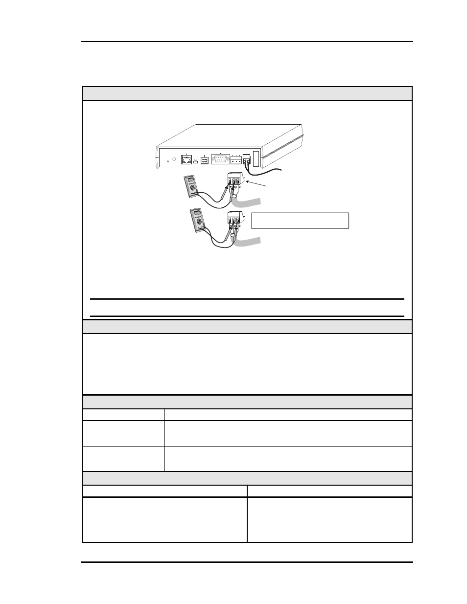
Checking the Network Loop at CommLink IV
Diagram
+
-
+
-
T-To-G
+2.4 VDC
To
+3.3 VDC
R-To-G
+2.4 VDC
to
+3.3 VDC
Note: Measured T-G and R-G Voltages
should be within 0.1 VDC of each other.
Communications
Loop
Disconnected
CommLink IV
Set Your Meter
To Read DC Volts
+
-
+
-
To
24 VAC
Power
Supply
MODEM
RS-232
Serial #
COMPUTER
USB
10/100
ETHERNET
DIAG
24
V
T G R
GN
D
485 LOOP POWER
ACT
LNK
USB
Co
nf
ig
No
rm
al
The indicated values are typical of a normal system; actual readings may deviate slightly
due to the number of units connected and other system specific factors.
Note: All of the connected Zone Managers should be powered up for this test.
Overview
Tip The Loop LED (located on the front panel) should “flicker” when the CommLink IV
is attempting to communicate with the Zone Managers. There is a noticeable change
in the flicker when the loop is disconnected, if you observe a normal functioning unit.
When the loop is reconnected it may take up to 60 seconds before the CommLink IV
re-establishes communications with the Zone Managers.
Measurements
Network Loop
Acceptable Range
T - G (SHLD)
2.4-to-3.3 Volts DC (Measured T-G and R-G Voltages should be
within 0.1 VDC of each other)
R - G (SHLD)
2.4-to-3.3 Volts DC (Measured T-G and R-G Voltages should be
within 0.1 VDC of each other)
Action
Condition
Action
If voltages are outside the acceptable range
or T-G and R-G readings differ from each
other by more than 0.1 VDC
One or more of the Zone Manager
MiniLinks has a damaged Network driver
chip. Disconnect Zone Managers one at a
time to isolate the problem.