2 becoming familiar with the zone controller, Figure 4-12: zone controller component layout – Auto-Zone Control Systems Auto-Zone Plus Systems Installation & Operation (Version 03A) User Manual
Page 190
Section 4
Auto-Zone Plus
4-40
Start-Up and Troubleshooting
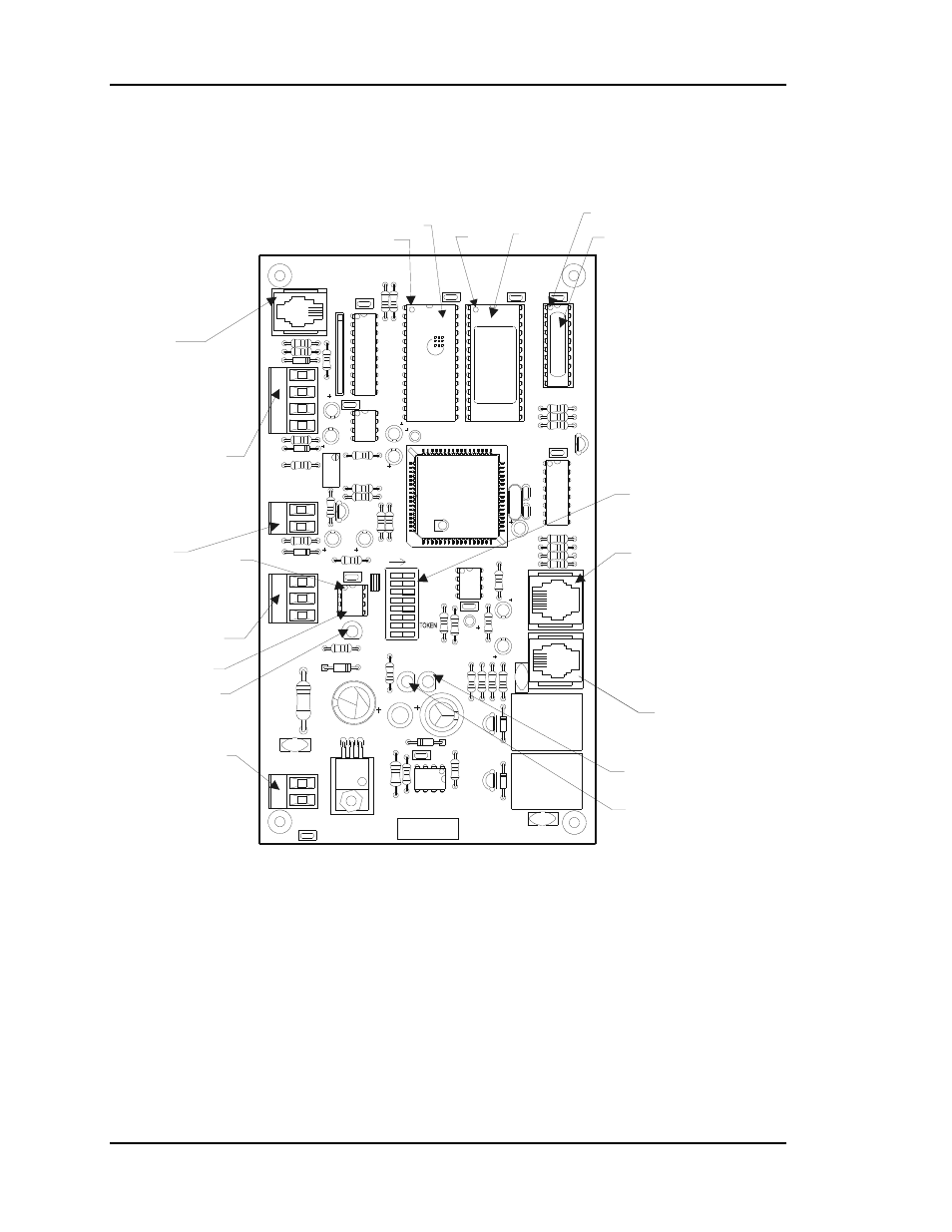
3.2 Becoming Familiar with the Zone
Controller
24VAC
GND
T
SHLD
G
+VS
AUX1
AUX2
GND
TEMP
GND
Optional
Airflow Sensor
Input
Relay Expansion
Board Jack
Damper Actuator
Jack
24 VAC Power
Diagnostic Blink LED
Communications REC LED
Power LED
Address Switch
Communications
Driver Chip
RS-485
Communications
Auxiliary Inputs
Room Sensor
Input
EPROM
RAM
Pin 1
Pin 1
PAL
Pin 1
PIN 1
CX4
R2
8
R24
7824
GND
R1
7
R1
6
U7
PO
W
E
R
R26
YS101562
REV
. 3
24VAC
D4
VR1
L1
C7
D3
SCAN
R2
1
REC
C6
R1
4
CX10
U1
1
COMM
C1
5
R25
SW
1
U1
0
16
32
NET
4
8
2
1
U6
ADDRESS
EW
DO
G
C1
1
R2
0
R1
9
ADD
VREF
ADJ
T'STAT
R32
D6
C1
4
C1
3
R2
7
C8
R23
C1
0
P.U.
R22
CX9
C9
U9
U8
D5
RN1
AIRFLOW
R3
4
R1
8
CX8
U4
R1
5
Q3
D2
K2
V2
PJ
2
R1
00
R1
2
R1
1
Q2
D1
K1
R9
R1
3
V1
ACTUA
T
OR
C4
R8
CX6
C5
C3
PJ
1
CX
5
R6
R7
R5
R4
C2
EXP
ANSI
ON
CX2
PA
L
X1
C1
EPROM
R1
R2
R3
U2
Q1
CX1
U3
CX3
U1
P.U.
O
I
D7
R33
U5
P.U.
485
DR
V
C16
V3
R3
5
PJ
3
OF
F
Figure 4-12:
Zone Controller Component Layout