10 typical zone manager wiring diagram, Figure 4-10: typical zone manager wiring diagram, Hvac unit terminals – Auto-Zone Control Systems Auto-Zone Plus Systems Installation & Operation (Version 03A) User Manual
Page 181: Network comm loop, Economizer actuator, Vfd (optional), Bypass interface board (optional)
Auto-Zone Plus
Section 4
Start-Up and Troubleshooting
4-31
2.2.10
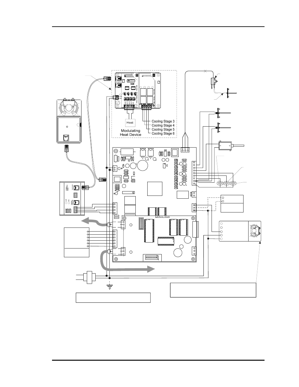
Typical Zone Manager Wiring Diagram
Local Communications Loop
To Zone Controllers
And System Manager
Note: 24 VAC Power Connection Must Be
Wired So That All Ground Wires Remain Common
Return Air Temperature
Sensor
Supply Air Temperature
Sensor
Line
Voltage
.
HVAC Unit
Terminals
24 VAC Only
Auto-Zone Plus Zone Manager
Bypass/Slave
Actuator
(Optional)
R
E
D
B
LK
G
R
N
Static Pressure
Pick-up Probe
Static Pressure
Sensor
Splice As
Required
FRP
Tubing
(By Others)
LO
HI
GND
24VAC
Note: See Specific Manufacturer’s Wiring Diagrams
For Other Models Or Brands Of Actuators If Used.
(Actuator Must Be Capable of Accepting 0-10 or 2-10
VDC Signal)
HEAT2
HEAT1
COOL2
COOL1
FAN
R
8
C
S
W
1
1
6
A
B
2
4
A
D
D
LOCAL
LOOP
T
SH
R
TB3
COMM
T
SH
R
32
16
8
4
1
2
R9
R10
R8
PWR
V4
V3
CLOSE
OPEN
FDBK
REC
GND
GND
24VAC
AUX1
OPEN
K
1
NETWORK
LOOP
Network
Comm Loop
SH
R
T
CLOSE
K
2
NE5090
ANALOG
OUTPUTS
A2
G
TB2
A1
N.O.
EXHAUST
CONTACTS
GND
GND
AUX3
AUX2
7824
D
25
U
1
4
V
R
3
R
4
0
ADJUST
5.11V
C
2
7
7812
C
2
6
V
R
2
D1
D3
D4
D2
PJ1
P
R
E
S
S
U
R
E
S
E
N
S
O
R
J
A
C
K
+
5V
R7
OAT
RAT
+12V
SAT
ANALOG
INPUTS
G
N
D
S
IG
T
R
SHIELD
T
R
SHIELD
Outdoor Air Temperature
Sensor
AUX3
Forced
Occupied
Mode
AUX1 Heat/Cool
Disable Or Fan
Proving
AUX2
Filter
Alarm
R
G
Y1
Y2
W1
W2
Economizer Actuator
133 IN-LB
AF24-SR
1 COM
2 +
3 Y1
4 Y2
5 U
BELIMO
1
1
0
0
OE352 Expansion Base Board
W/ OE355 4 Analog Output &
OE357 4 Relay Expansion Board
(Optional)
Output Signal
(0-10 VDC)
+
-
VFD
(Optional)
FDBK
OPEN
GND
GND
PJ1
PJ2
LD
2
LD
1
OPEN
CLOSE
CLOSE
TB
1
TB
2
Bypass Interface
Board
(Optional)
Expansion Board For
Modulating Heating & 6
Stage Cooling Configuration.
Shown. Other Configuration
Options Are Available.
See Figure 2-4
Figure 4-10:
Typical Zone Manager Wiring Diagram