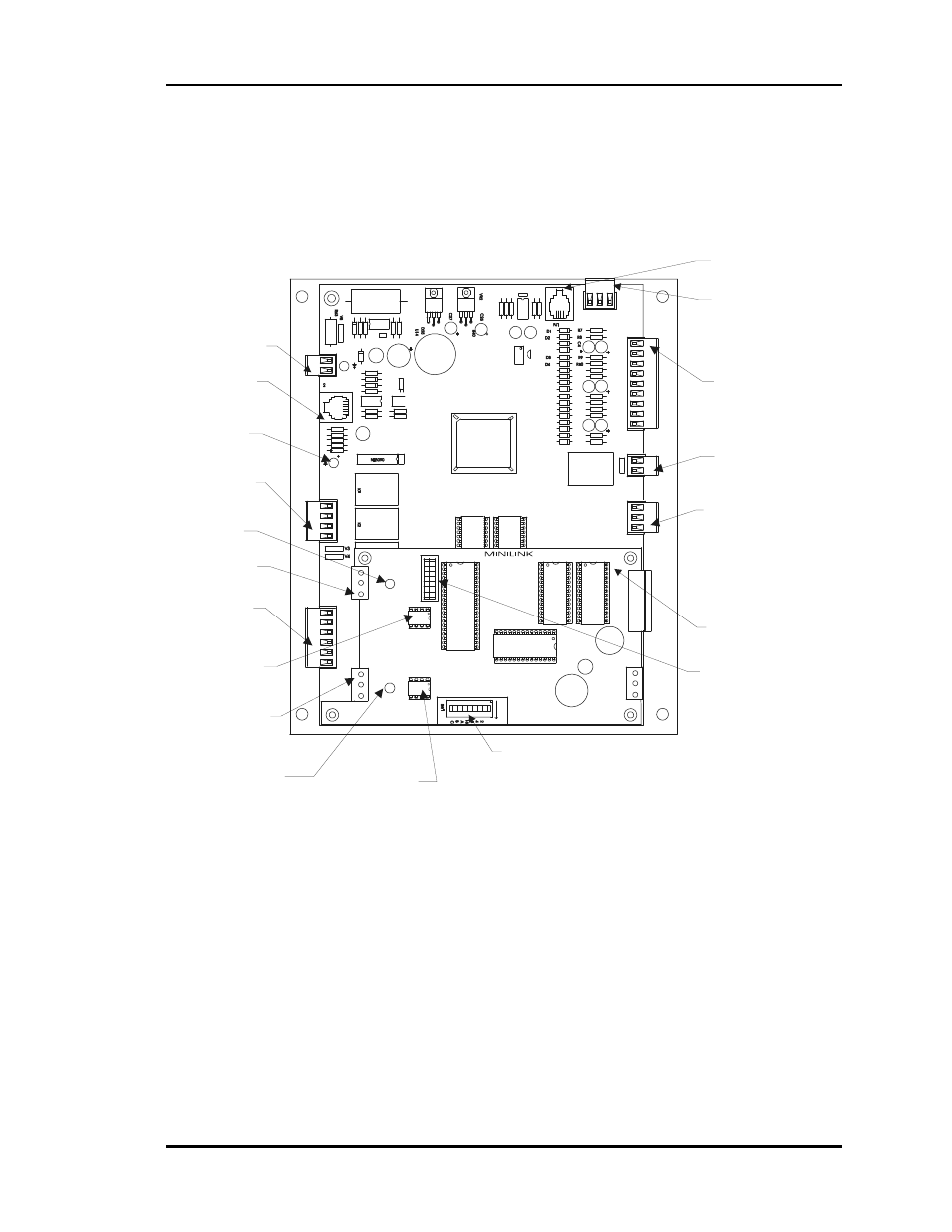
2 becoming familiar with the zone manager, Figure 4-8: zone manager component layout – Auto-Zone Control Systems Auto-Zone Plus Systems Installation & Operation (Version 03A) User Manual
Page 175
Auto-Zone Plus
Section 4
Start-Up and Troubleshooting
4-25
2.2 Becoming Familiar with the Zone
Manager
HEAT2
HEAT1
COOL2
COOL1
FAN
R
AD
D
LO
O
P
T
SH
R
TB3
LOOP
T
SH
R
32
16
8
4
1
2
I C EXP PORT
POWER
CLOSE
OPEN
FDBK
REC
GND
GND
TB2
24VAC
AUX1
OPEN
NET
W
ORK
SH
R
CLOSE
T
ANALOG
OUTPUTS
A2
G
TB2
A1
N.O.
CONTACTS
EXHAUST
GND
GND
AUX3
AUX2
ADJUST
5.11V
PR
ES
SU
RE
SE
N
SO
R J
AC
K
+5
V
INPUTS
OAT
RAT
+12V
SAT
ANALOG
G
N
D
S
IG
T
B
12
HVAC Unit
Connector
Analog Input
Connector
Static
Pressure
Sensor
Terminals
Static Pressure
Sensor Jack
Powered
Exhaust
Connector
Economizer/VFD
Connector
Minilink
Board
Bypass Damper
Connector
Network Loop
Connector
Network Loop
Communications
Driver Chip
Network Loop
Communications
LED
Zone Manager
Communications
LED
24 VAC
Power
Connector
Expansion Board
Connector
Local Loop
Communications
LED
Local Loop
Communications
Driver Chip
Zone Manager
Address Switch
( Always Set To 17 )
MiniLink Address
Switch. Each MiniLink
Board Must Be
Addressed Uniquely
Local Loop
Connector
Figure 4-8:
Zone Manager Component Layout