Commlink iv wiring, Plus 2-46 design guide, Figure 2-33: commlink iv wiring – Auto-Zone Control Systems Auto-Zone Plus Systems Installation & Operation (Version 03A) User Manual
Page 78
Section 2
Auto-Zone
Plus
2-46
Design
Guide
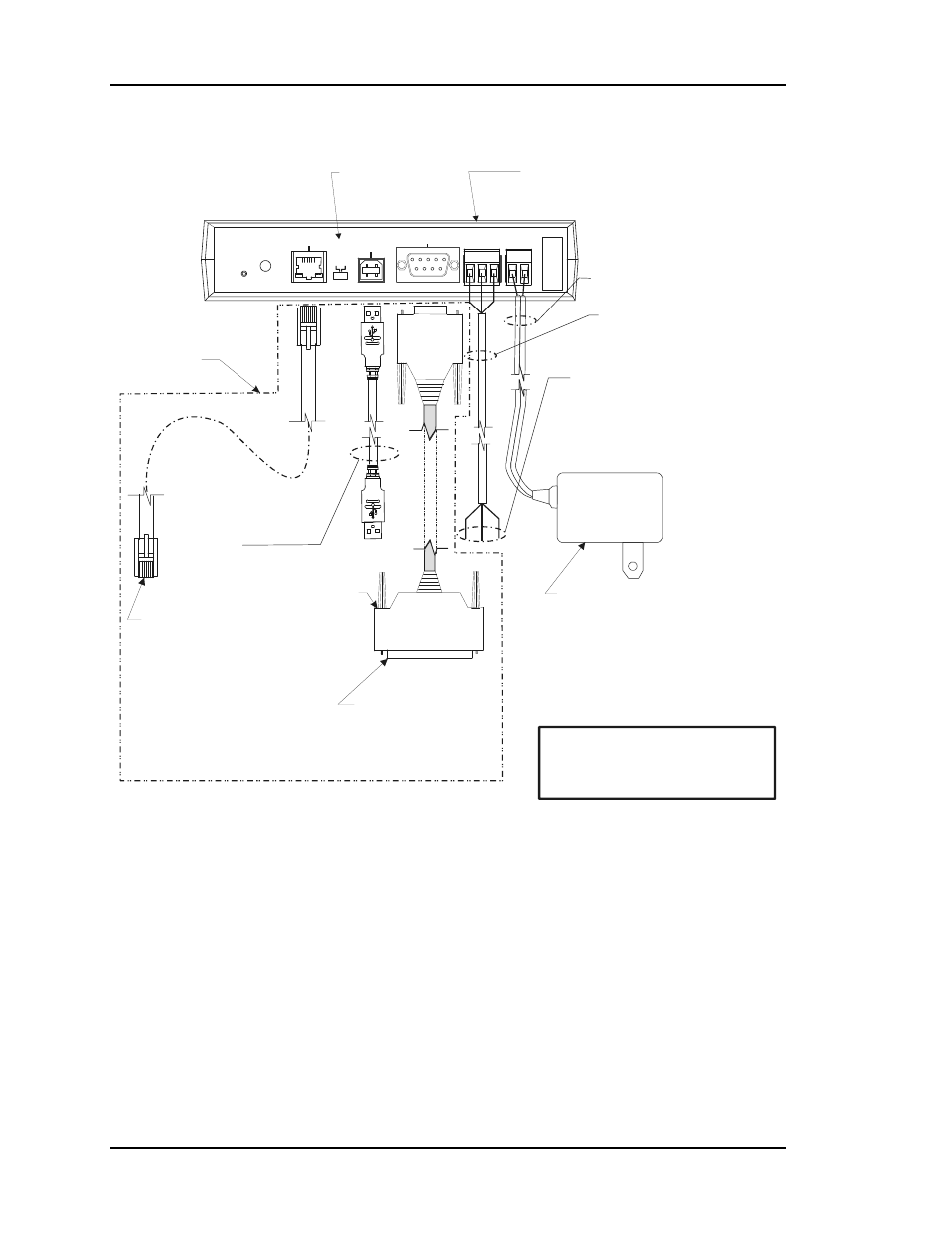
CommLink IV Wiring
24 VAC Power
If Desired A 24 VAC Transformer
Rated At 12 VA Minimum May Be
Used Instead Of The Supplied Power Pack.
Use 18 Gauge Minimum 2 Conductor Wire
Between The Transformer & CommLink IV
Terminals
(Not
Included)
120 to 24 VAC Power Pack
(Included) Connect To 120/1/60 Duplex
Receptacle (By Others)
USB Cable (Included). Connect
This Cable To Your Computer USB
Port For Directly Connecting To
CommLink IV. Also Used For
Advanced Configuration of
CommLink IV.
CommLink IV
Communications Interface
Notes:
1) Use 18 Gauge Minimum 2 Conductor Twisted Pair With Shield Cable Belden #82760 Or Equivalent
(Not Included) To Connect The CommLink IV To The Zone Manager MiniLink.
2) For Direct Connection Via USB, Your Computer Must Have An Unused USB Port Available. Drivers
For Your USB Port Are Provided On A CD Supplied With The CommLink IV And Will Need To Be
Installed On Your Computer In Order For It To Function Correctly. Please Follow The Directions In
The CommLink IV USB Driver Installation Section (Included) To Install And Configure The USB
Drivers.
3) The CommLink IV Cannot Communicate With The Control System Through Its Ethernet Port And
USB Port At The Same Time.
4) All Wiring Must Conform To Applicable Federal, State & Local Electrical Wiring Codes.
18 Gauge 2 Conductor
With Shield (Not Included)
See Note 1
Connect To The
Zone Manager MiniLink
See Note 1
MODEM
RS-232
Serial #
COMPUTER
USB
10/100
ETHERNET
DIAG
24V
T G R
GN
D
485 LOOP POWER
ACT
LNK
USB
Co
n
fi
g
No
rm
al
Optional - Prefabricated Ft. Long CAT5
Ethernet Cable (Included With Optional OE415-
02 IP Module Kit).
If A Longer
Ethernet Cable Is Required, You Will Need To
Obtain (From Others) And Install An Ethernet
Cable Of The Required Length For Your
Installation.
10
Connect To A 10/100 Base-T
Ethernet Router On Your LAN.
When An Optional Remote
Link Is Used, Connect This
Cable To CommLink IV And
Remote Link As Shown. Cable
Is Included With Remote Link.
Molded Modem Cable.
Part #HZ000098
Supplied With RemoteLink II
9 P
in
Fe
ma
le
25 Pin
Male
WARNING!
If You Are Using The IP Module
With Your CommLink, Do Not Have Your
Ethernet Connection And USB Connection
Connected At The Same Time. This Could
Cause Unreliable Communications.
Optional Items Not
Required For
CommLink Only
Installations.
USB Switch
Should Be Set
To Normal
Figure 2-33:
CommLink IV Wiring