0 start-up, 1 blink codes – Auto-Zone Control Systems Auto-Zone Plus Systems Installation & Operation (Version 03A) User Manual
Page 201
Auto-Zone Plus
Section 4
Start-Up and Troubleshooting
4-51
5.0 Start-Up
5.1 Blink
Codes
The Zone Controller and the CV Controller use an on board LED to indicate various
diagnostic conditions during powerup and operation. The Zone Controller LED is labeled
“SCAN” and the CV Unit LED is labeled “LED2”. Starting with power up the LED blink
codes are as follows:
• Off for five seconds
• SCAN LED blinks the board address (Address 14 = 14 blinks)
• Five second pause
• Twenty second time delay – LED2 blinks twenty times
• LED2 stays on continuous during damper calibration (No damper calibration
on the CV Unit)
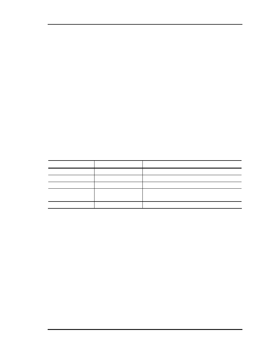
• Status code is repeatedly blinked every ten seconds to indicate controller
status:
Priority
No. of Blinks
Status
Lowest 1
Normal
Operation
- 2
Override
Active
-
3
Bad Zone or Airflow Sensor
- 4
Damper
Failure
(Not used on CV Units)
Highest 5
Communication
Failure
Table 4-1:
Diagnostic LED2 Blink Codes
Only the highest priority failure code will be shown. You must correct the highest priority
alarm before other problems will be indicated.