5 switch configuration, 1 switch power, 5 switch configuration 4.5.1 switch power – Comtech EF Data CRS-311 User Manual
Page 100
CRS-311 1:1 Redundancy Switch
Revision 7
Modem, RMI/TMI, and Switch Configuration MN/CRS311.IOM
4–10
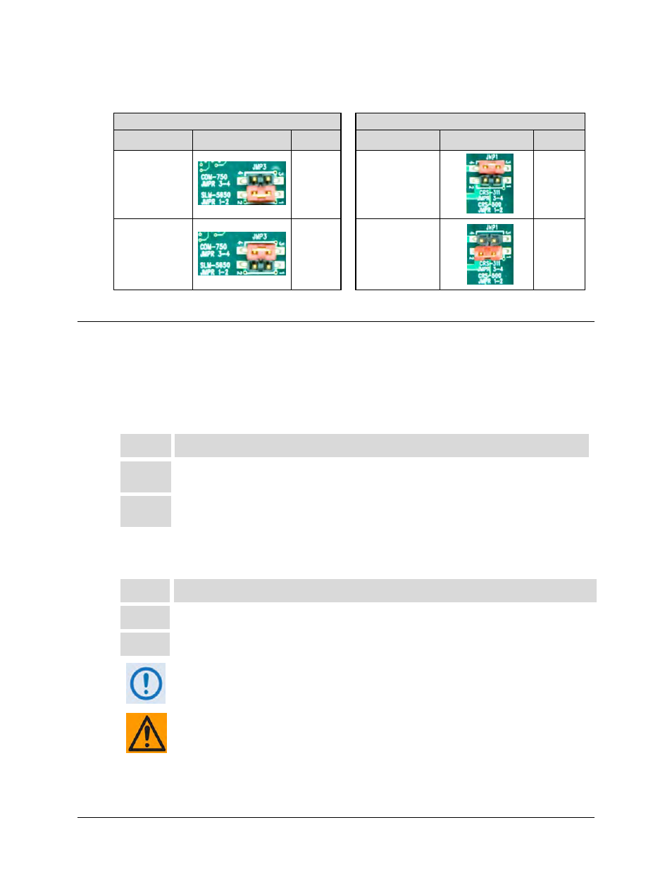
Table 4-2. CRS-515 TMI Factory-configured Jumper Settings
Modem Jumper ‘JMP3’
Switch Jumper ‘JMP1’
Control Setting
Jumpers
Settings
Control Setting
Jumpers
Settings
SLM-
5650/5650A
AS SHIPPED
Pins
1 to 2
jumped
CRS-311
AS SHIPPED
Pins
3 to 4
jumped
CDM-750
Pins
3 to 4
jumped
CRS-500
Pins
1 to 2
jumped
4.5
Switch Configuration
4.5.1 Switch Power
Follow these steps to connect the power cords:
Step
Task
1
Each CRS-311 is supplied with two power cords. Connect the female end of the supplied
power cords (one to each power supply power input).
2
Plug both power cords into the power source(s). The CRS-311 will power ON.
Note: The auto-sensing power supplies do not require any adjustments.
If only one power supply module is used, mask the fault for the unused power supply as follows:
Step
Task
1
Go to the CONFIG: MASKS Æ SW-ALARMS menu.
2
Select to mask the unused power supply.
The power supplies contain two fuses, one each for line and neutral connections
(or L1, L2 where appropriate). These are contained within the body of the
connector, behind the small plastic flap.
For continued operator safety, always replace the fuses with the correct type and
rating. For 115/230 volt AC operation, use T1A (slow‐blow) 20 mm fuses.