Appendix a. cable drawings, A.1 introduction, A.2 user / utility cables – Comtech EF Data CRS-311 User Manual
Page 145
A-1
Appendix A. CABLE DRAWINGS
A.1
Introduction
This appendix identifies the cables used with the CRS‐311 1:1 Redundancy Switch. It divides these cables into three usage categories: User/Utility
Cables, Control Cables, and Data Traffic / IF Cables. Each category / appendix section includes illustrations of the cables’ technical specifications;
additionally, the tables featured in the Control or Data Traffic / IF Cables sections cross‐reference to the illustrations found in
Chapter 3. CABLES
AND CONNECTIONS
.
All dimensions, where specified in the illustrations provided in this appendix, are in inches.
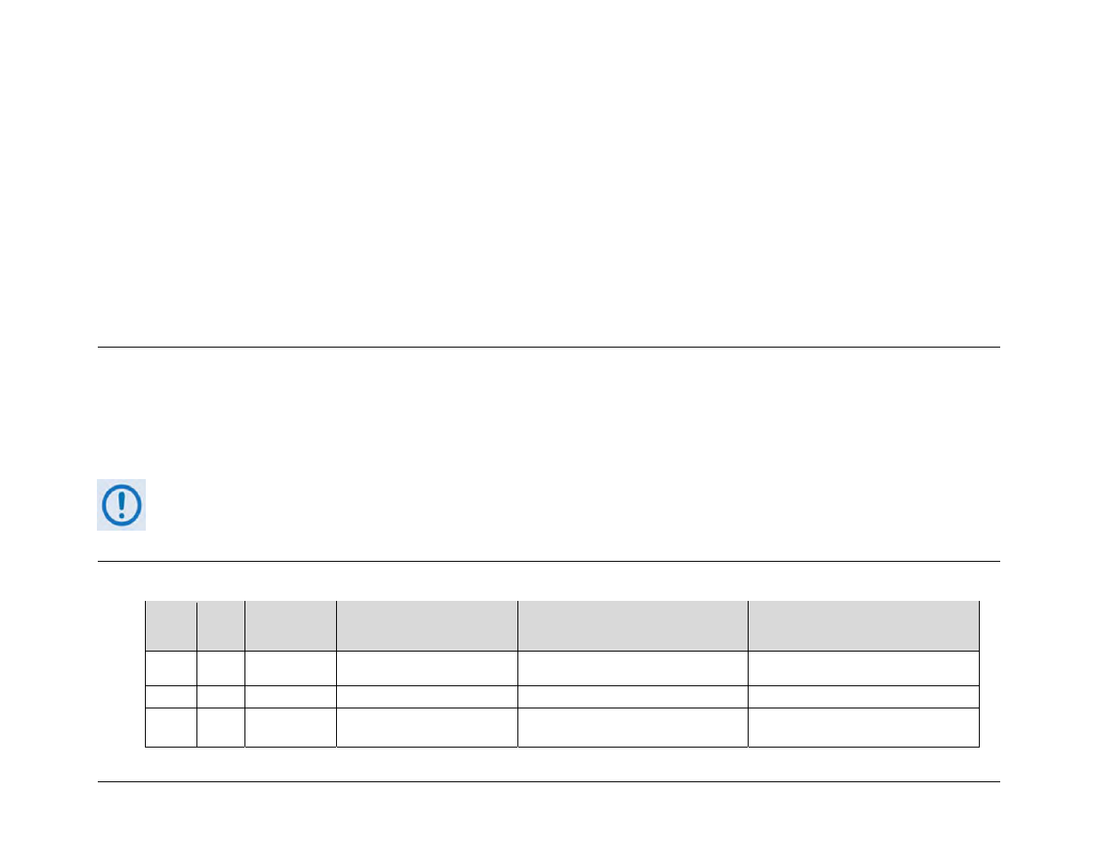
A.2
User / Utility Cables
App. A
FIG
REF
Ch. 3
FIG
CEFD CABLE
P/N
DESCRIPTION
USED WITH CRS-311 Æ …
USED FOR (DATA TYPE)
A-1 N/A
N/A
N/A
User
Data
EIA-530 Æ EIA-422/449 DCE
(Data Conversion Equipment)
A-2 N/A
N/A
N/A
User
Data
EIA-530
Æ
V.35 DCE
A-3
N/A
N/A
N/A
User EIA-232 Switch M&C / Firmware Update CRS-311 Remote Control Æ PC Serial Port