B.2.4 crs-336 – hssi connector (hd-50f) – Comtech EF Data CRS-311 User Manual
Page 175
CRS-311 1:1 Redundancy Switch
Revision 7
Appendix B
MN/CRS311.IOM
B–7
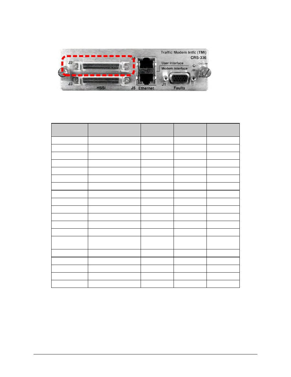
B.2.4 CRS-336 – HSSI Connector (HD-50F)
Table B‐7 indicates the pinout for the HD‐50F Mini‐D/SCSI‐II “HSSI” User Interface connector:
“J2” on the CRS‐336 TMI.
Table B-7. “J2” HSSI User Data Connector
Pin # (+, -)
Signal Function
HSSI Signal
RS613 Circuit
Circuit
Direction
1, 26
Signal Ground
SG
102
2, 27
Receive Timing
RT
115
from DCE
3, 28
DCE Available
CA
107
from DCE
4, 29
Receive Data
RD
104
from DCE
5, 30
N/A
N/A
N/A
N/A
6, 31
Send Timing
ST
114
from DCE
7, 32
Signal Ground
SG
102
8, 33
DTE Available
TA
108/2
to DCE
9, 34
Terminal Timing
TT
113
to DCE
10, 35
N/A
N/A
N/A
N/A
11, 36
Send Data
SD
103
to DCE
12, 37
N/A
N/A
N/A
N/A
13, 38
Signal Ground
SG
102
14,15,17, 18, 39-
43
Reserved (to DCE)
not used
16 Tx_Carrier_Off_L
1, 3
CO
undefined
from
DTE
19, 44
Signal Ground
SG
102
20
Carrier Detect (lock)
1, 2
CD undefined
from
DCE
21-24, 46-49
Reserved (to DTE)
undefined
not used
25, 50
Signal Ground
SG
102
Notes:
1. Noted signal function names are non‐HSSI defined signals. On Cisco™ routers, there is
no connection to those pins.
2. TTL ‐ output.
3. TTL or RS‐232 (active low) input.