B.2 tmi user data connectors – Comtech EF Data CRS-311 User Manual
Page 172
CRS-311 1:1 Redundancy Switch
Revision 7
Appendix B
MN/CRS311.IOM
B–4
B.2
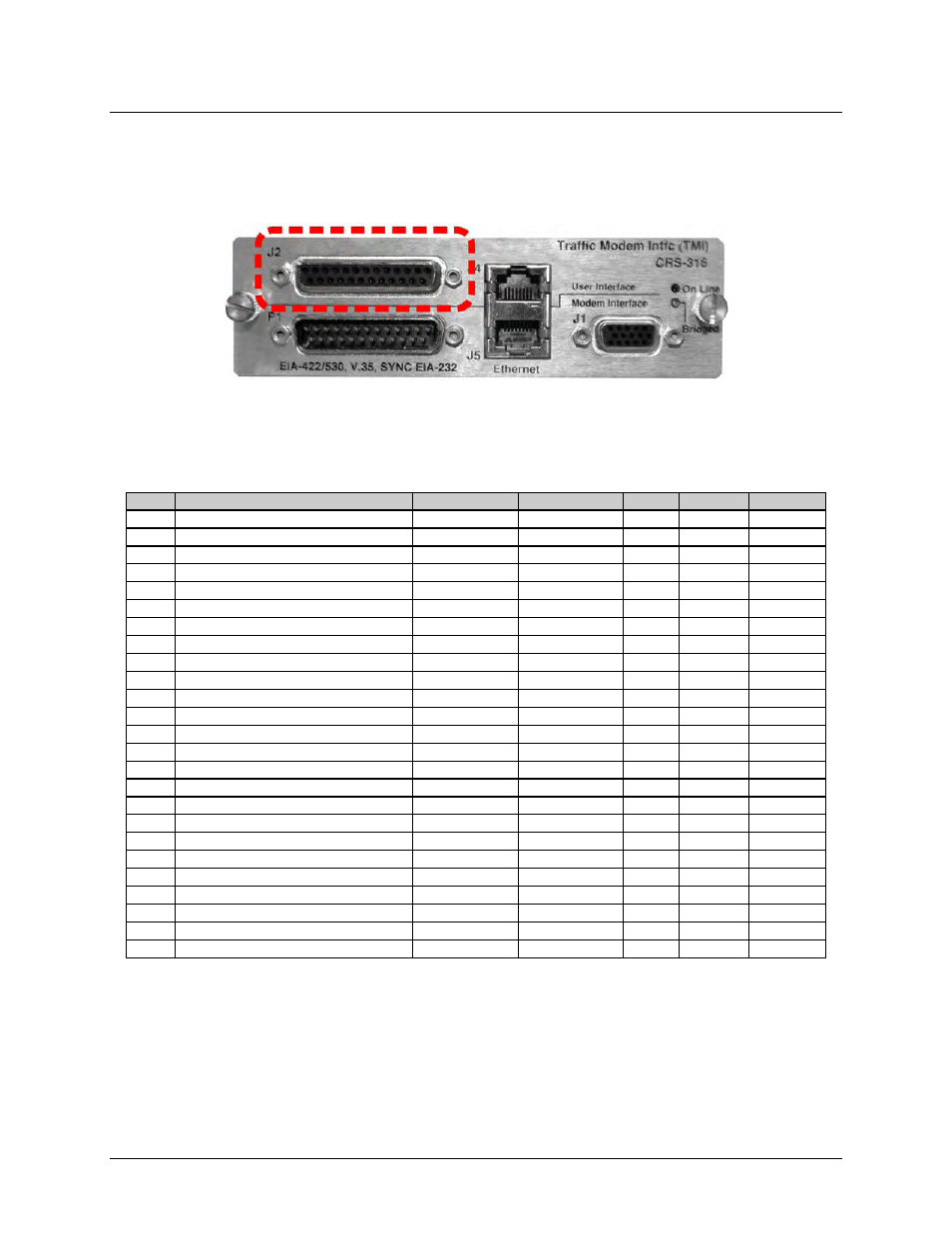
TMI User Data Connectors
B.2.1 CRS-316 – EIA-422/530, V.35, Sync EIA-232 Connector (DB-25F)
Table B‐4 indicates the pinout for the DB‐25F EIA‐232/422/V.35 User Interface connector: “J2” on
the CRS‐316 TMI.
Table B-4. “J2” EIA-422/530 / V.35 / Sync EIA-232 User Data Connector
Pin #
Generic Signal Description
Direction
EIA-422/EIA-530
V.35
EIA-232
Circuit No.
1 Shield
-
Shield
FG
AA
101
14
Transmit Data B
DTE to Modem
SD B
SD B
-
103
2 Transmit Data A
DTE to Modem
SD A
SD A
BA
103
15
Internal Transmit Clock A
Modem to DTE
ST A
SCT A
DB
114
3 Receive Data A
Modem to DTE
RD A
RD A
BB
104
16
Receive Data B
Modem to DTE
RD B
RD B
-
104
4 Request to Send A / Ready for Receiving A
DTE to Modem
RS A
RS A
17
Receive Clock A
Modem to DTE
RT A
SCR A
DD
115
5 Not
used
18 Not
used
6 DCE Ready A
Modem to DTE
DM_A
DM_A
19
Request to Send B / Ready for Receiving B
DTE to Modem
RS B
RS B
7 Signal
Ground
-
SG
SG
AB
102
20 Not
used
8 Receiver Ready A
Modem to DTE
RR A
RLSD *
CF
109
21 Not
used
9 Receive Clock B
Modem to DTE
RT B
SCR B
-
115
22
DCE Ready B
Modem to DTE
DM_B
DM_B
10 Receiver Ready B
Modem to DTE
RR
B
-
109
23 Not
Used
11 Transmit Clock B
DTE to Modem
TT B
SCTE B
-
113
24
Transmit Clock A
DTE to Modem
TT A
SCTE A
DA
113
12 Internal Transmit Clock B
Modem to DTE
ST B
SCT B
-
114
25 Not
Used
13 Not
used
Notes:
1. Receiver‐Ready is an EIA‐232‐level control signal on a V.35 interface.
2. 'B' signal lines are not used for EIA‐232 applications.
3.
For X.21 operation, use the EIA‐422 pins, but ignore Receive Clock if the modem is DTE, and ignore
Transmit clocks if the modem is DCE.