Comtech EF Data CRS-311 User Manual
Page 193
CRS-311 1:1 Redundancy Switch
Revision 7
Appendix E
MN/CRS311.IOM
E–3
Step Task
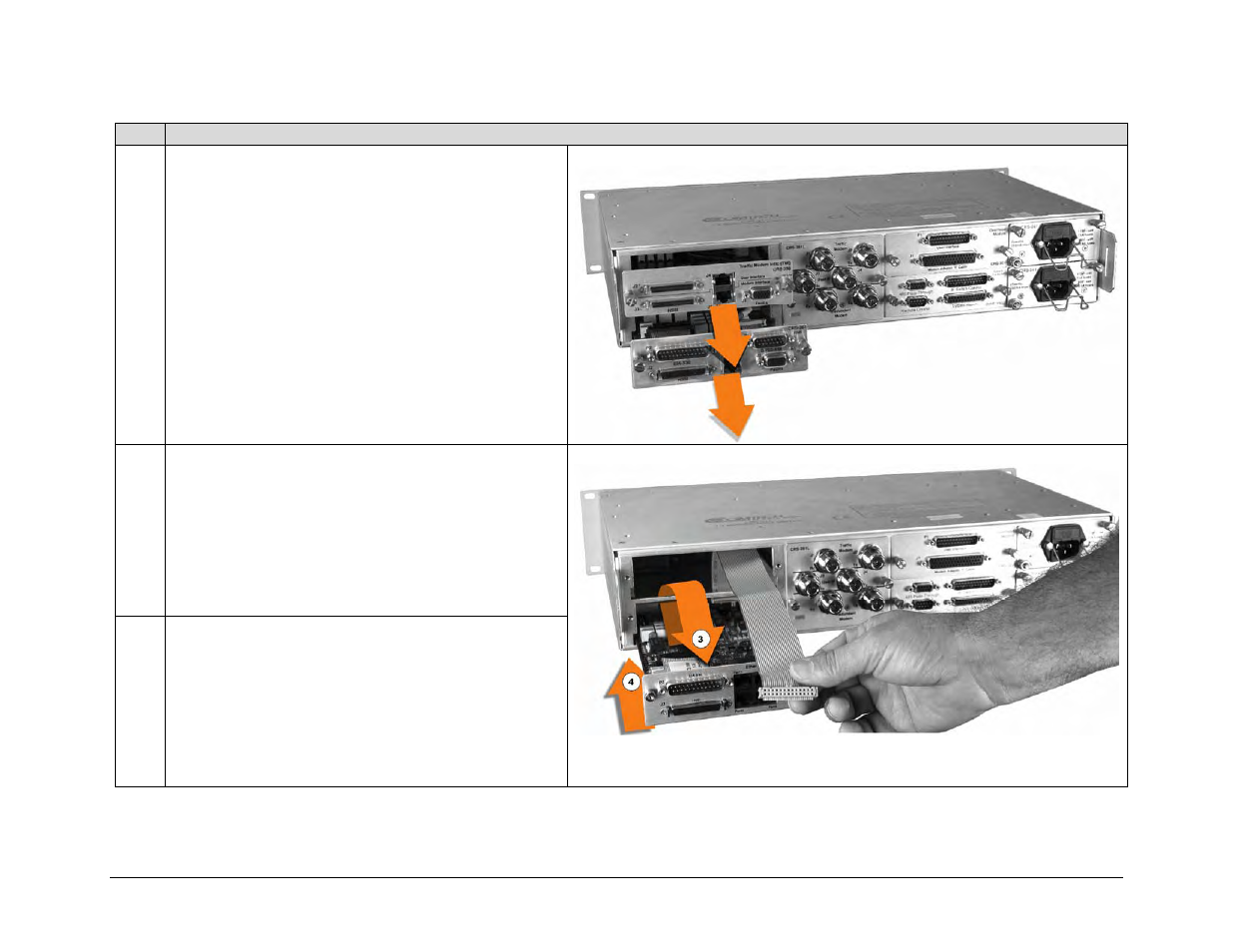
2
Prepare the CRS-311 Switch Chassis for retrofit by
loosening the thumbscrews then removing the existing
RMI and TMI modules.
(Note: The configuration shown here is for illustrative
purposes only. The actual redundant/traffic modem
interfaces, power modules, and controller interfaces, as
originally installed, may vary.)
3
Thread the CA-0000089 Ribbon Cable’s unconnected
(loose) end through the bottom (RMI) slot opening into
the CRS-311 chassis, looping the end out through the
top (TMI) slot opening.
4
Install the CRS-505 RMI into its chassis slot while
pulling lightly on the unconnected (loose) end of the
CA-0000089 Ribbon Cable. Engage the RMI until it is
properly seated in the receptacle on the chassis
backplane.
Do not tighten the CRS-505 RMI’s thumbscrews at this
time.