2 front panel, 3 rear panel – Comtech EF Data CRS-311 User Manual
Page 31
CRS-311 1:1 Redundancy Switch
Revision 7
Introduction
MN/CRS311.IOM
1–7
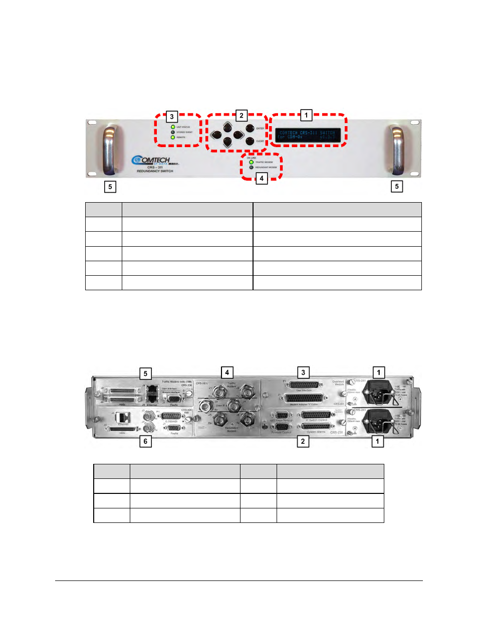
1.3.2 Front Panel
Figure 1‐4 shows the CRS‐311 front panel. The CRS‐311 is constructed as a 2RU‐high, rack‐
mounting chassis that can be freestanding if desired. Handles afford easy placement into and
removal from a rack.
Feature Description
Function
1
Vacuum Fluorescent Display (VFD)
Displays menus, prompts, and messages
2
6-button keypad
Menu navigation
3
(3) Light-Emitting Diodes (LEDs)
Switch status monitoring
4
(2) Light-Emitting Diodes (LEDs)
Modem status monitoring
5 Rack
Handles
Installation
into / removal from a rack
Figure 1-4. CRS-311 Front Panel
1.3.3 Rear Panel
Figure 1‐5 shows the rear panel of a typical CRS‐311 operational configuration.
Feature Description
Feature Description
1
CRS-241 AC Power Supply
4
CRS-281L IF Switch Module
2
CRS-230 System Controller
5
CRS-336 TMI
3
CRS-351 Overhead Module
6
CRS-306 RMI
Figure 1-5. CRS-311 Rear Panel Configuration Example