3 rmi jumper configuration reference (crs-505) – Comtech EF Data CRS-311 User Manual
Page 98
CRS-311 1:1 Redundancy Switch
Revision 7
Modem, RMI/TMI, and Switch Configuration MN/CRS311.IOM
4–8
4.3
RMI Jumper Configuration Reference (CRS-505)
This section is provided for RMI identification purposes only. All RMIs are shipped
preconfigured and do not require user adjustments.
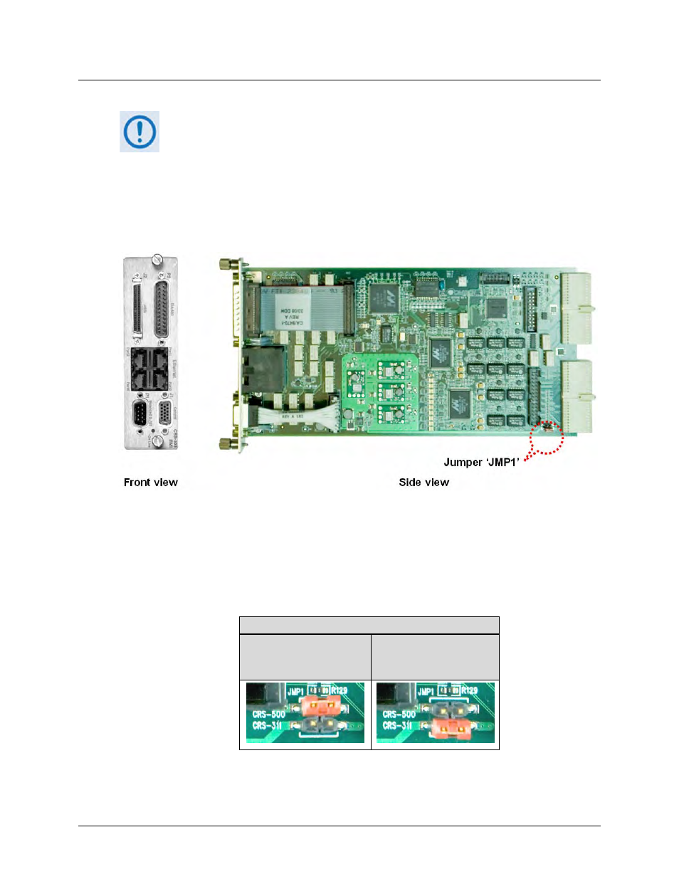
The CRS‐505 RMI (CEFD P/N PL‐0000293) comes preconfigured for proper operation with the
CRS‐311 1:1 Redundancy Switch using SLM‐5650/5650A modems. Configuration of the ‘JMP1’
jumper setting on the PCB determines whether the module is configured for use with the CRS‐
311 1:1 Redundancy Switch, or for use with the CRS‐500 M:N Redundancy System. Figure 4‐3
shows the ‘JMP1’ jumper location identified on the CRS‐505 PCB.
Figure 4-3. CEFD P/N PL-0000293 CRS-505 RMI PCB
Table 4‐1 illustrates the ‘JMP1’ jumper settings that are factory‐set for each RMI that is used
with the CRS‐311 1:1 Redundancy Switch and SLM‐5650/5650A modems.
Table 4-1. CRS-505 RMI Factory-configured Jumper Settings
CRS-505 Jumper ‘JMP1’ Control Settings
CRS-500
Pins 1 to 2 jumped
CRS-311
Pins 3 to 4 jumped
AS SHIPPED