4 tmi jumper configuration reference (crs-515) – Comtech EF Data CRS-311 User Manual
Page 99
CRS-311 1:1 Redundancy Switch
Revision 7
Modem, RMI/TMI, and Switch Configuration MN/CRS311.IOM
4–9
4.4
TMI Jumper Configuration Reference (CRS-515)
This section is provided for TMI identification purposes only. All TMIs are shipped
preconfigured and do not require user adjustments.
The CRS‐515 TMI (CEFD P/N PL‐0000294) comes preconfigured for proper operation with the
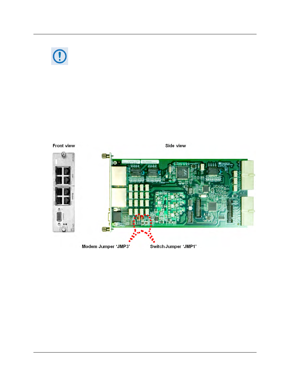
CRS‐311 1:1 Redundancy Switch using SLM‐5650/5650A modems. Figure 4‐4 shows (from left)
the ‘JMP3’ and ‘JMP1’ jumper location identified on the CRS‐515 PCB. Configuration of the
jumper setting determines the designated operation:
• The ‘JMP3’ pin group 1‐4 establishes operation of the TMI for use with the CDM‐750 or
SLM‐5650/5650A modems.
• The ‘JMP1’ pin group 1‐4 establishes operation of the CRS‐515 TMI for use with the
CRS‐311 1:1 Redundancy Switch, or with the CRS‐500 M:N Redundancy System.
Figure 4-4. CEFD P/N PL-0000294 CRS-515 TMI PCB
Table 4‐2 illustrates the ‘JMP3’ and ‘JMP1’ jumper settings that are factory‐set for each CRS‐515
TMI that is used with the CRS‐311 1:1 Redundancy Switch and SLM‐5650/5650A modems.