4 modem redundancy configuration, 1 switch to cdm-qx/qxl redundancy configuration – Comtech EF Data CRS-311 User Manual
Page 93
CRS-311 1:1 Redundancy Switch
Revision 7
Modem, RMI/TMI, and Switch Configuration MN/CRS311.IOM
4–3
Using the modem’s manual, configure the Traffic Modem for the proper Rx and Tx IF, power
settings, modulation, code rates, and traffic data settings.
If the modem does not meet these listed requirements, contact Comtech EF Data.
Firmware upgrades are free and you may download these files from the CEFD Web
page. Hardware revision upgrades must be performed at CEFD.
For User‐to‐Switch or User‐to‐Modem addressing schemes, see
Appendix C. Addressing
Scheme Information
.
4.2.4 Modem Redundancy Configuration
4.2.4.1 Switch to CDM-Qx/QxL Redundancy Configuration
The CRS‐311‐to‐CDM‐Qx/QxL redundancy configuration uses an external EIA‐485 multi‐drop
communication cable.
The CDM‐Qx/QxL can be configured in many different ways, but for a CRS‐311 application, the
CDM‐Qx/QxL should be configured only as one modem – i.e., containing one modulator and one
demodulator module, which must be grouped to act as a modem. See the CDM‐Qx/QxL
Installation and Operation Manual for more information.
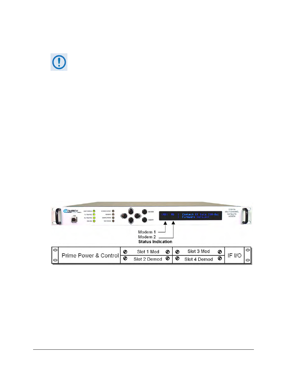
As shown in Figure 4‐1, Modem 1 resides in Slots 1 and 2. Modem 2 is contained in Slots 3 and
4. The Switch can use either modem.
(Top) Front Panel
(Bottom) Rear Panel Schematic
Figure 4-1. CDM-Qx/QxL Serial Communication Configuration
The CDM‐Qx/QxL chassis has a configurable EIA‐485 base address – which applies for Modem 1
– and an offset, which is added to the base‐address if addressing Modem 2. The EIA‐485
addresses are selected via the front panel menu:
CONFIG
Æ REMOTE
.
The Switch addresses each CDM‐Qx/QxL modem based on which TMI it is attached to, with
addresses at increments of 100. For example, with a Switch with address 0, the Qx/QxL Traffic